20 - FORM NO. 56041704
American-Lincoln
6150
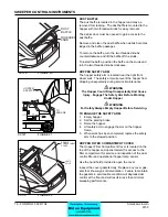
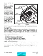
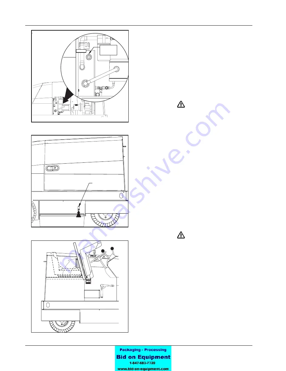
HYDRAULIC RESERVOIR LEVEL SIGHT GAUGE
The sight gauge is located on the side of the hydraulic
reservoir in the engine compartment. The sight gauge is
used to indicate the level of fl uid in the reservoir. Fluid
level must be visible in the sight gauge when the hopper
is in the down position.
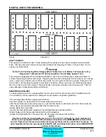
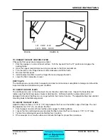
MAIN BROOM COMPARTMENT DOORS
The main broom compartment doors are located behind
the front tires on both sides of the sweeper. The doors
provide access to the main broom for service or inspec-
tion.
WARNING
Operate Only When Lids, Doors, And Access Panels
Are Securely Closed.
Open the right side door to remove or replace the main
broom. The right side door is an integral part of the main
broom drive system and must be closed for operation.
Open the left side broom door for inspection. Check the
drive hub for banding and shrink wrap which have a
tendency to get tangled in the broom driver.
To open the main broom door, reach inside the hole in
the door and lift up on the latch handle.
The door latch will automatically engage when the door
is closed.
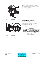
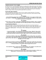
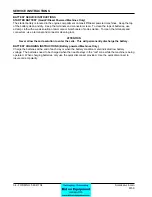
SEAT COMPARTMENT COVER
The seat compartment cover opens to allow easy access
to various components which will need to be inspected or
serviced periodically. The cover opens forward and has
a safety latch to hold the cover in the open position.
WARNING
Lead acid batteries generate gases which can cause
an explosion. Keep sparks and fl ames away from
batteries. NO SMOKING. Charge batteries only in
area with good ventilation and keep the seat cover
open to vent explosive hydrogen gas.
On battery powered machines the compartment below
the seat contains the charging connector for the
batteries. Use the safety latch to hold the cover open
while charging the batteries.
On Gas/Diesel/LP powered machines the seat
compartment contains the fuel tank.
American-Lincoln
MODEL NO.
SERIAL NO.
WARNING
c0731/0005
American-Lincoln
MAIN BROOM
COMPARTMENT
LATCH
LIFT TO OPEN
C-0729
C0728
FIGURE 26
C0729
FIGURE 27
C0731
FIGURE 28
SWEEPER CONTROLS/INSTRUMENTS
C-0728
HYDRAULIC
SIGHT
GAUGE
Summary of Contents for 6150
Page 39: ...FORM NO 56042480 6150 IC 4 06 5 REAR WHEEL 07 10 ...
Page 41: ...FORM NO 56042480 6150 IC 6 06 5 VAC FAN 07 10 ...
Page 45: ...FORM NO 56042480 6150 IC 10 06 5 FLAP ASSEMBLY WHEEL WELL 07 3 C 1227 ...
Page 51: ...FORM NO 56042480 6150 IC 16 06 5 C1250 H46 H43 H39 H47 H53 SIDE BROOM ASSEMBLY 07 3 ...
Page 53: ...FORM NO 56042480 6150 IC 18 06 5 SIDE BROOM LIFT SYSTEM 07 10 ...
Page 57: ...FORM NO 56042480 6150 IC 22 06 5 BROOM CHAMBER FLAPS SEALS 07 10 ...
Page 59: ...FORM NO 56042480 6150 IC 24 06 5 BRAKE PEDAL 80805 1 6 05 07 3 ...
Page 63: ...FORM NO 56042480 6150 IC 28 06 5 SEAT FLOOR ASSEMBLY 07 10 ...
Page 71: ...FORM NO 56042480 6150 IC 36 06 5 CONTROL RELIEF VALVE 3 CYL KUBOTA GAS DIESEL 07 3 ...
Page 73: ...FORM NO 56042480 6150 IC 38 06 5 FWD REV CONTROL 2 CYL KAWASAKI GAS 07 10 ...
Page 75: ...FORM NO 56042480 6150 IC 40 06 5 FW REV CONTROL 3 CYL KUBOTA GAS DIESEL 07 3 ...
Page 81: ...FORM NO 56042480 6150 IC 46 06 5 FUEL TANK GAS 07 10 ...
Page 83: ...FORM NO 56042480 6150 IC 48 06 5 FUEL TANK DIESEL 07 10 ...
Page 87: ...FORM NO 56042480 6150 IC 52 06 5 80806 2 2 05 HOPPER COVERS GASKET ASSEMBLY ...
Page 91: ...FORM NO 56042480 6150 IC 56 06 5 H26 H80 H86 H26 H98 H22 C 1207 9701 DUMP DOOR ...
Page 97: ...FORM NO 56042480 6150 IC 62 06 5 HYDRAULIC PUMP 3 CYL KUBOTA GAS DIESEL 07 3 80851 SHT01 ...
Page 99: ...FORM NO 56042480 6150 IC 64 06 5 ENGINE COVER 30 25 32 31 80813 0 3 07 ...
Page 101: ...FORM NO 56042480 6150 IC 66 06 5 80841 8 05 ACCESS COVER ASSEMBLY ...
Page 105: ...FORM NO 56042480 6150 IC 70 06 5 ENGINE 3 CYL KUBOTA GAS 07 10 ...
Page 107: ...FORM NO 56042480 6150 IC 72 06 5 ENGINE 3 CYL KUBOTA DIESEL 07 10 ...
Page 109: ...FORM NO 56042480 6150 IC 74 06 5 ENGINE 3 CYL DUAL FUEL LP 07 10 ...
Page 113: ...FORM NO 56042480 6150 IC 78 06 5 80839revF 8 05 HYDRAULIC HOSE DIAGRAM 2 CYL ...
Page 125: ...FORM NO 56042480 6150 IC 90 06 5 DECALS 08 7 ...
Page 127: ...FORM NO 56042480 6150 IC 92 06 5 DECALS continued 07 10 ...
Page 129: ...FORM NO 56042480 6150 IC 94 06 5 C1335 7 04 2 CYLINDER LP CE MODELS ONLY ...
Page 136: ...101 FORM NO 56042480 6150 IC 06 5 HYDRAULIC SCHEMATIC 2 CYL GAS LP DIESEL 08 7 ...
Page 138: ...103 FORM NO 56042480 6150 IC 06 5 HYDRAULIC SCHEMATIC 3 CYL KUBOTA GAS DIESEL ...


