American-Lincoln
FORM NO. 56041704 - 33
6150
TO CHANGE THE DUST CONTROL FILTER
Change the fi lter panel when damage is evident.
1. Park the sweeper on a smooth level surface. Turn the key switch to the “O” position and engage the
parking brake.
2. Open the hopper compartment cover to gain access to the fi lter compartment.
3. Turn the latch on the hinged frame counter-clockwise and lift the frame.
4. Remove
the
fi lter panel.
5. Install
replacement
fi lter, lower the hinged frame and engage the latch.
6. Lower
the
fi lter compartment cover.
DUST FLAPS
The dust fl aps are very important to sweeping and dust control and are susceptible to damage and should be
inspected daily and maintained in good condition.
TO CHECK THE DUST FLAPS
The dust fl aps are used on the wheel well, broom chamber, and broom door. Inspect the fl aps daily and
replace any fl ap that shows signs of wear or deterioration. All fl aps should be replaced when worn or
damaged to the point that they can no longer perform their normal function. The adjustable fl aps have slotted
mounting holes to facilitate adjustment.
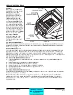
TO ADJUST THE DUST FLAPS
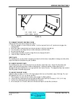
Adjust the fl aps so there is a 1/8” to 1/16” Gap between the fl oor and the bottom edge of the fl aps. The rear
fl ap adjustment is 1/16” (16 cm.) above the fl oor.
1. Park Sweeper on a smooth level surface and engage the Parking Brake.
2. Loosen the Flap retaining screws and adjust the fl ap to clear the fl oor and leave a 1/16” to 1/8” Gap.
3. Tighten Flap retaining screws while holding fl ap in position.
4. Drive sweeper on a smooth surface and recheck the fl aps for proper fl oor clearance.
SERVICE INSTRUCTIONS
1/1
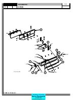
6"
SET DOOR
F
LAP
E
V
EN
W
ITH
F
LOOR
P4488A
FIGURE
34
Summary of Contents for 6150
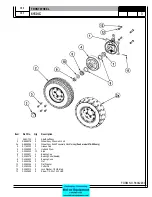
Page 39: ...FORM NO 56042480 6150 IC 4 06 5 REAR WHEEL 07 10 ...
Page 41: ...FORM NO 56042480 6150 IC 6 06 5 VAC FAN 07 10 ...
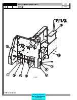
Page 45: ...FORM NO 56042480 6150 IC 10 06 5 FLAP ASSEMBLY WHEEL WELL 07 3 C 1227 ...
Page 51: ...FORM NO 56042480 6150 IC 16 06 5 C1250 H46 H43 H39 H47 H53 SIDE BROOM ASSEMBLY 07 3 ...
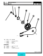
Page 53: ...FORM NO 56042480 6150 IC 18 06 5 SIDE BROOM LIFT SYSTEM 07 10 ...
Page 57: ...FORM NO 56042480 6150 IC 22 06 5 BROOM CHAMBER FLAPS SEALS 07 10 ...
Page 59: ...FORM NO 56042480 6150 IC 24 06 5 BRAKE PEDAL 80805 1 6 05 07 3 ...
Page 63: ...FORM NO 56042480 6150 IC 28 06 5 SEAT FLOOR ASSEMBLY 07 10 ...
Page 71: ...FORM NO 56042480 6150 IC 36 06 5 CONTROL RELIEF VALVE 3 CYL KUBOTA GAS DIESEL 07 3 ...
Page 73: ...FORM NO 56042480 6150 IC 38 06 5 FWD REV CONTROL 2 CYL KAWASAKI GAS 07 10 ...
Page 75: ...FORM NO 56042480 6150 IC 40 06 5 FW REV CONTROL 3 CYL KUBOTA GAS DIESEL 07 3 ...
Page 81: ...FORM NO 56042480 6150 IC 46 06 5 FUEL TANK GAS 07 10 ...
Page 83: ...FORM NO 56042480 6150 IC 48 06 5 FUEL TANK DIESEL 07 10 ...
Page 87: ...FORM NO 56042480 6150 IC 52 06 5 80806 2 2 05 HOPPER COVERS GASKET ASSEMBLY ...
Page 91: ...FORM NO 56042480 6150 IC 56 06 5 H26 H80 H86 H26 H98 H22 C 1207 9701 DUMP DOOR ...
Page 97: ...FORM NO 56042480 6150 IC 62 06 5 HYDRAULIC PUMP 3 CYL KUBOTA GAS DIESEL 07 3 80851 SHT01 ...
Page 99: ...FORM NO 56042480 6150 IC 64 06 5 ENGINE COVER 30 25 32 31 80813 0 3 07 ...
Page 101: ...FORM NO 56042480 6150 IC 66 06 5 80841 8 05 ACCESS COVER ASSEMBLY ...
Page 105: ...FORM NO 56042480 6150 IC 70 06 5 ENGINE 3 CYL KUBOTA GAS 07 10 ...
Page 107: ...FORM NO 56042480 6150 IC 72 06 5 ENGINE 3 CYL KUBOTA DIESEL 07 10 ...
Page 109: ...FORM NO 56042480 6150 IC 74 06 5 ENGINE 3 CYL DUAL FUEL LP 07 10 ...
Page 113: ...FORM NO 56042480 6150 IC 78 06 5 80839revF 8 05 HYDRAULIC HOSE DIAGRAM 2 CYL ...
Page 125: ...FORM NO 56042480 6150 IC 90 06 5 DECALS 08 7 ...
Page 127: ...FORM NO 56042480 6150 IC 92 06 5 DECALS continued 07 10 ...
Page 129: ...FORM NO 56042480 6150 IC 94 06 5 C1335 7 04 2 CYLINDER LP CE MODELS ONLY ...
Page 136: ...101 FORM NO 56042480 6150 IC 06 5 HYDRAULIC SCHEMATIC 2 CYL GAS LP DIESEL 08 7 ...
Page 138: ...103 FORM NO 56042480 6150 IC 06 5 HYDRAULIC SCHEMATIC 3 CYL KUBOTA GAS DIESEL ...


