12 - FORM NO. 56041704
American-Lincoln
6150
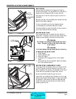
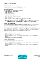
FOOT BRAKE
The foot brake pedal is located on the fl oor of the
operator’s compartment to the left of the directional
control pedal.
To stop, apply foot pressure to the brake pedal.
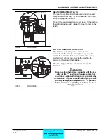
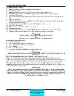
PARKING BRAKE
The parking brake lever is located on the operator’s
compartment left side panel near the fl oor. When en-
gaged the parking brake “locks” the foot pedal in the
down position.
-
To engage the parking brake, place the lever in the
upright position.
-
To disengage the parking brake, move the lever
forward.
-
To Adjust The Parking brake “Grab” Turn the knob
on the top of the lever.
-
To increase “Grab” Turn the knob in a clockwise
direction.
-
To decrease “Grab” Turn the knob in a counter-
clockwise direction.
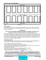
FOOT PEDAL
The Foot Pedal is located on the fl oor of operator’s
compartment to the right of the brake pedal. The
foot pedal provides control of direction/speed and
has an automatic safety feature that limits foot pedal
travel while the hopper is raised. The pedal height is
adjustable to provide for operator comfort.
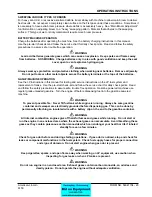
TO GO FORWARD:
Place pressure on the upper por-
tion of the pedal. Speed increases when additional
pressure is placed on the pedal.
TO GO BACKWARD:
Put pressure on the lower portion
of the pedal. Speed increases when additional pressure
is placed on the pedal.
-To increase braking action while sweeper is moving
forward, gently put pressure on the lower portion of the
pedal.
-To Increase braking action while traveling in reverse,
gently put pressure on the upper portion of the pedal.
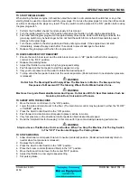
To adjust the foot pedal height for operator comfort
1. Remove the hairpin cotter from the adjustment pin.
2. Remove the adjustment pin from the foot pedal
assembly.
3. Align the holes in the lower bracket with one of the
four adjustment holes on the foot pedal to set the
foot pedal height.
4. With the holes aligned at the desired height, insert
the adjustment pin
5. Reinstall the hairpin cotter.
LIGHTS
CIRCUT BREAKERS
1
2
3
4
5
6 OPTION
WORK
LIGHT
GLOW
PLUG
American-Lincoln
FILTER
SHAKER
DUST
CONTROL
SIDE BROOM
MAIN BROOM
ENGINE
SPEED
IDLE
OFF
ACC
IGN/ON
START
1
2
HOURS
0 0 0 0 0
1/10
0
1/2
4/4
FUEL
FOOT
BRAKE
TO
APPLY
BRAKE
C-0704
FOR
WARD
REVERSE
NEUTRAL
ADJUSTMENT
PIN
ADJUSTMENT
HOLES
HAIRPIN
COTTER
C-0706
LIGHTS
CIRCUT BREAKERS
1
2
3
4
5
6 OPTION
WORK
LIGHT
GLOW
PLUG
American-Lincoln
FILTER
SHAKER
DUST
CONTROL
SIDE BROOM
MAIN BROOM
O
I
HOURS
0 0 0 0 0
1/10
0
1/2
4/4
FUEL
C-0705
PARKING
BRAKE
TO
RELEASE
BRAKE
C0704
FIGURE 5
C0705
FIGURE 6
C0706
FIGURE 7
SWEEPER CONTROLS/INSTRUCTIONS
Summary of Contents for 6150
Page 39: ...FORM NO 56042480 6150 IC 4 06 5 REAR WHEEL 07 10 ...
Page 41: ...FORM NO 56042480 6150 IC 6 06 5 VAC FAN 07 10 ...
Page 45: ...FORM NO 56042480 6150 IC 10 06 5 FLAP ASSEMBLY WHEEL WELL 07 3 C 1227 ...
Page 51: ...FORM NO 56042480 6150 IC 16 06 5 C1250 H46 H43 H39 H47 H53 SIDE BROOM ASSEMBLY 07 3 ...
Page 53: ...FORM NO 56042480 6150 IC 18 06 5 SIDE BROOM LIFT SYSTEM 07 10 ...
Page 57: ...FORM NO 56042480 6150 IC 22 06 5 BROOM CHAMBER FLAPS SEALS 07 10 ...
Page 59: ...FORM NO 56042480 6150 IC 24 06 5 BRAKE PEDAL 80805 1 6 05 07 3 ...
Page 63: ...FORM NO 56042480 6150 IC 28 06 5 SEAT FLOOR ASSEMBLY 07 10 ...
Page 71: ...FORM NO 56042480 6150 IC 36 06 5 CONTROL RELIEF VALVE 3 CYL KUBOTA GAS DIESEL 07 3 ...
Page 73: ...FORM NO 56042480 6150 IC 38 06 5 FWD REV CONTROL 2 CYL KAWASAKI GAS 07 10 ...
Page 75: ...FORM NO 56042480 6150 IC 40 06 5 FW REV CONTROL 3 CYL KUBOTA GAS DIESEL 07 3 ...
Page 81: ...FORM NO 56042480 6150 IC 46 06 5 FUEL TANK GAS 07 10 ...
Page 83: ...FORM NO 56042480 6150 IC 48 06 5 FUEL TANK DIESEL 07 10 ...
Page 87: ...FORM NO 56042480 6150 IC 52 06 5 80806 2 2 05 HOPPER COVERS GASKET ASSEMBLY ...
Page 91: ...FORM NO 56042480 6150 IC 56 06 5 H26 H80 H86 H26 H98 H22 C 1207 9701 DUMP DOOR ...
Page 97: ...FORM NO 56042480 6150 IC 62 06 5 HYDRAULIC PUMP 3 CYL KUBOTA GAS DIESEL 07 3 80851 SHT01 ...
Page 99: ...FORM NO 56042480 6150 IC 64 06 5 ENGINE COVER 30 25 32 31 80813 0 3 07 ...
Page 101: ...FORM NO 56042480 6150 IC 66 06 5 80841 8 05 ACCESS COVER ASSEMBLY ...
Page 105: ...FORM NO 56042480 6150 IC 70 06 5 ENGINE 3 CYL KUBOTA GAS 07 10 ...
Page 107: ...FORM NO 56042480 6150 IC 72 06 5 ENGINE 3 CYL KUBOTA DIESEL 07 10 ...
Page 109: ...FORM NO 56042480 6150 IC 74 06 5 ENGINE 3 CYL DUAL FUEL LP 07 10 ...
Page 113: ...FORM NO 56042480 6150 IC 78 06 5 80839revF 8 05 HYDRAULIC HOSE DIAGRAM 2 CYL ...
Page 125: ...FORM NO 56042480 6150 IC 90 06 5 DECALS 08 7 ...
Page 127: ...FORM NO 56042480 6150 IC 92 06 5 DECALS continued 07 10 ...
Page 129: ...FORM NO 56042480 6150 IC 94 06 5 C1335 7 04 2 CYLINDER LP CE MODELS ONLY ...
Page 136: ...101 FORM NO 56042480 6150 IC 06 5 HYDRAULIC SCHEMATIC 2 CYL GAS LP DIESEL 08 7 ...
Page 138: ...103 FORM NO 56042480 6150 IC 06 5 HYDRAULIC SCHEMATIC 3 CYL KUBOTA GAS DIESEL ...


