American-Lincoln
FORM NO. 56041704 - 11
6150
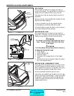
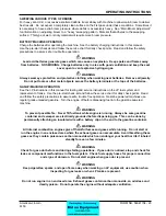
KEY SWITCH
The keyed ignition switch is located on the instrument
panel to the right of the steering column. The key switch
is a four position switch that controls power to the sweep-
er systems and accessories.
BATTERY POWERED MACHINES
The “O ” position will shut off power to the machine pro-
pulsion and sweeping systems.
The “I” position provides power to all sweeper systems
and accessories.
GAS/DIESEL/LP POWERED MACHINES
The “O” position will shut off the engine.
The “I” position provides power to all sweeper systems
and accessories.
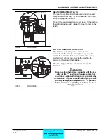
THROTTLE
The engine speed is controlled by a locking push-pull
control which is located on the operator’s compartment
side console.
The position of the throttle determines the operating
speed of the engine. The position is variable from idle to
max engine speed and may be adjusted to suit operating
conditions.
The locking feature of the engine throttle control consists
of a rubberized push button that unlocks the control for
adjustment.
Push down on the button while positioning the control to
the desired setting, then release the button to unlock the
throttle in place.
Pull up on the throttle to increase engine speed.
Push down on the throttle to decrease engine speed.
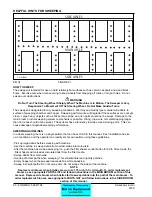
FUEL GAUGE
The fuel gauge is located on the instrument panel and
indicates the level of fuel in the tank. The fuel gauge
is powered by the key switch. The key switch must be
in the “I” position for the fuel gauge to work. The fuel
gauge is not included on machines that use Battery or
Liquid Propane fuel.
SWEEPER CONTROLS/INSTRUMENTS
0
1/2
4/4
FUEL
C0703/0005
CHOKE
HORN
THROTTLE
THR
O
TTLE
PUSH BUTTON
TO RELEASE
C0701-1
FIGURE 2
C0702
FIGURE 3
C0703
FIGURE 4
O
I
KEY
SWITCH
C0701-1
Accessory
Position
Start
Position
Summary of Contents for 6150
Page 39: ...FORM NO 56042480 6150 IC 4 06 5 REAR WHEEL 07 10 ...
Page 41: ...FORM NO 56042480 6150 IC 6 06 5 VAC FAN 07 10 ...
Page 45: ...FORM NO 56042480 6150 IC 10 06 5 FLAP ASSEMBLY WHEEL WELL 07 3 C 1227 ...
Page 51: ...FORM NO 56042480 6150 IC 16 06 5 C1250 H46 H43 H39 H47 H53 SIDE BROOM ASSEMBLY 07 3 ...
Page 53: ...FORM NO 56042480 6150 IC 18 06 5 SIDE BROOM LIFT SYSTEM 07 10 ...
Page 57: ...FORM NO 56042480 6150 IC 22 06 5 BROOM CHAMBER FLAPS SEALS 07 10 ...
Page 59: ...FORM NO 56042480 6150 IC 24 06 5 BRAKE PEDAL 80805 1 6 05 07 3 ...
Page 63: ...FORM NO 56042480 6150 IC 28 06 5 SEAT FLOOR ASSEMBLY 07 10 ...
Page 71: ...FORM NO 56042480 6150 IC 36 06 5 CONTROL RELIEF VALVE 3 CYL KUBOTA GAS DIESEL 07 3 ...
Page 73: ...FORM NO 56042480 6150 IC 38 06 5 FWD REV CONTROL 2 CYL KAWASAKI GAS 07 10 ...
Page 75: ...FORM NO 56042480 6150 IC 40 06 5 FW REV CONTROL 3 CYL KUBOTA GAS DIESEL 07 3 ...
Page 81: ...FORM NO 56042480 6150 IC 46 06 5 FUEL TANK GAS 07 10 ...
Page 83: ...FORM NO 56042480 6150 IC 48 06 5 FUEL TANK DIESEL 07 10 ...
Page 87: ...FORM NO 56042480 6150 IC 52 06 5 80806 2 2 05 HOPPER COVERS GASKET ASSEMBLY ...
Page 91: ...FORM NO 56042480 6150 IC 56 06 5 H26 H80 H86 H26 H98 H22 C 1207 9701 DUMP DOOR ...
Page 97: ...FORM NO 56042480 6150 IC 62 06 5 HYDRAULIC PUMP 3 CYL KUBOTA GAS DIESEL 07 3 80851 SHT01 ...
Page 99: ...FORM NO 56042480 6150 IC 64 06 5 ENGINE COVER 30 25 32 31 80813 0 3 07 ...
Page 101: ...FORM NO 56042480 6150 IC 66 06 5 80841 8 05 ACCESS COVER ASSEMBLY ...
Page 105: ...FORM NO 56042480 6150 IC 70 06 5 ENGINE 3 CYL KUBOTA GAS 07 10 ...
Page 107: ...FORM NO 56042480 6150 IC 72 06 5 ENGINE 3 CYL KUBOTA DIESEL 07 10 ...
Page 109: ...FORM NO 56042480 6150 IC 74 06 5 ENGINE 3 CYL DUAL FUEL LP 07 10 ...
Page 113: ...FORM NO 56042480 6150 IC 78 06 5 80839revF 8 05 HYDRAULIC HOSE DIAGRAM 2 CYL ...
Page 125: ...FORM NO 56042480 6150 IC 90 06 5 DECALS 08 7 ...
Page 127: ...FORM NO 56042480 6150 IC 92 06 5 DECALS continued 07 10 ...
Page 129: ...FORM NO 56042480 6150 IC 94 06 5 C1335 7 04 2 CYLINDER LP CE MODELS ONLY ...
Page 136: ...101 FORM NO 56042480 6150 IC 06 5 HYDRAULIC SCHEMATIC 2 CYL GAS LP DIESEL 08 7 ...
Page 138: ...103 FORM NO 56042480 6150 IC 06 5 HYDRAULIC SCHEMATIC 3 CYL KUBOTA GAS DIESEL ...


