450370 - 2
www.adclaundry.com
23
Using a Magnehelic
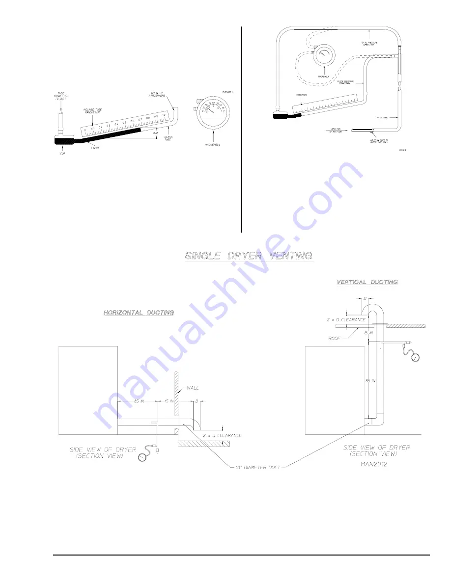
When measuring such small air pressures, the U-tube is often
not accurate enough. Such small differences in pressure are
most often measured by an inclined tube manometer or a
Magnehelic pressure gage as shown in
Illustration #2
.
Illus. #2
For convenience and accuracy, an instrument known as a Pitot
tube is used with the gage. The Pitot tube, as shown in
Illustration #3
, consists of two tubes – one within the other.
The inner tube measures the total pressure alone, while the
outer tube measures the static pressure alone.
To obtain the most accurate static pressure readings of a dryer,
the following guidelines should be conformed to. The reading
should be taken in a straight section of duct, a minimum of ten
(10) times the diameter of the duct (i.e. 10-inches [25.4 cm]
diameter duct, a straight section 100-inches [254 cm] in length).
The reading should be taken a minimum of 8-1/2 times the
diameter upstream of the dryer or nearest elbow, and 1-1/2
times the diameter downstream of the Pitot tube. The following
is an example showing the proper location to take a static
pressure reading.
In designing a dryer exhaust duct system, it is not necessary to compute the friction loss of the ductwork. The friction loss (static
pressure) is predetermined to not exceed 0.3 in WC (0.74 mb). This maximum allowable static pressure is the same for all model
dryers and is calculated to provide maximum dryer efficiency. It is necessary to determine the total equivalent length of the duct
system. The total equivalent length of the duct system is the actual length of the duct added to the equivalent length of all the
fittings. The equivalent length of a fitting, is the length of straight duct of the same size as the fitting in which the friction losses are
equal. Equivalent lengths must be determined for all elbows, as well as, any entries which may be incorporated into a common
duct system for multiple dryers. The total equivalent length is then used with the total cfm exhaust rating of the dryer(s) to calculate
the minimum round duct diameter. When designing a single common duct system for multiple dryers, each individual dryer
exhaust duct enters the main common duct.
Illus. #3


