22
American Dryer Corp.
450370 - 2
NOTE:
Fuse 1 is for computer power rated at 1/2-amp. If
fuse blows, it is a computer board fault. Fuse 2 is for 24V
control power rated at 5-amp. If fuse blows, it is a 24V
control fault.
S.A.F.E. System Theory of Operation
While the dryer is in an idle state or 20-seconds after the heat
turns off, the Phase 7 control monitors the S.A.F.E. system
probe located in the top of the tumbler chamber and records
the minimum temperature. If the minimum recorded S.A.F.E.
system probe temperature is no less than 120° F (48° C) and
the control detects a 50° rise in temperature, this will be the
trip point and the S.A.F.E. system routine will activate.
While a drying cycle is in process and the heat has turned on
at least once, the Phase 7 control monitors the exhaust
temperature transducer. If the drying cycle temperature set
point is set greater than 160° F (71° C) and the control detects
an exhaust temperature rise 25° F greater than set point, this
will be the trip point and the S.A.F.E. system routine will activate.
If set point is below 160° F (71° C) the trip point will be 185° F
(85° C).
Once the S.A.F.E. system routine is activated, water will be
injected into the tumbler chamber. Anytime water is being
injected into the tumbler; the tumbler drive will turn the load for
1-second every 15-seconds. This process will continue for a
minimum of 2 minutes. After 2 minutes has elapsed, the control
will check if the temperature remained above trip point, if so
water will remain on. The control will continue to check if
temperature is above trip point every 30-seconds. If the water
has been on for a constant 10 minutes, the water will be turned
off regardless of the temperature. If the temperature has
dropped below trip point, the control will turn off the water prior
to 10 minutes.
Static Pressure
The pressure of the air in sheet metal ducts is of great
importance for safe and efficient operation of the dryer. The
air pressures, as small as they are, have a large influence upon
the performance of the dryer. There are three (3) pressures
present within a duct. The velocity pressure, which is the
pressure due to the moving stream of air, the static pressure,
which is the outward push of the air against the walls of the
duct, and the total pressure, which is the sum of the static and
velocity pressures. Only the total and static pressures can be
measured. The velocity pressure is then calculated from the
difference between the two. The static pressure is the most
influential and determining factor in the design of a dryer duct
system. ADC recommends that the dryer exhaust duct static
pressure not exceed 0.3 in WC (0.74 mb).
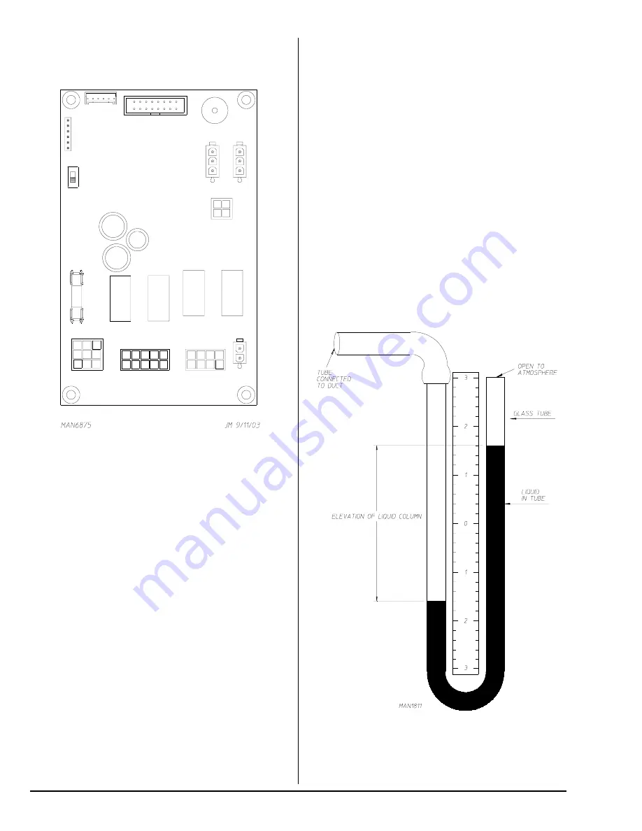
Gages used to measure such small air pressures utilize the
elevation of a column of water. This form of gage is called a
manometer. One form of this gage is known as a U-tube and
is shown in
Illustration #1
. When one end of the tube is
connected to the duct, the static (outward) pressure within the
duct forces the water column to be depressed in one leg of the
U-tube and up in the other. The elevation of the water column
in
Illustration #1
is 3.2 inches (8 mb).
Illus. #1


