C
OMMAND
M
ODE
D
ATA
F
ORMAT
SMD23E2 and SMD24E2 User Manual
ADVANCED MICRO CONTROLS INC.
86
Input Data Format (continued)
Status Word 0 Format (continued)
Bit 4: At_Home –
Set to “1” when a homing command has completed successfully, “0” at all other times.
Bit 3: Stopped –
Set to “1” when the motor is not in motion. Note that this is stopped for any reason, not
just a completed move. For example, an Immediate Stop command during a move will set this bit to
“1”, but the
Move_Complete
bit, (bit 7 above) will not be set.
Bit 2: In_Hold_State –
Set to “1” when a move command has been successfully brought into a Hold State.
Hold States are explained is the Controlling Moves In Progress section starting on page 22.
Bit 1: Moving_CCW –
Set to “1” when the motor is rotating in a counter-clockwise direction.
Bit 0: Moving_CW –
Set to “1” when the motor is rotating in a clockwise direction.
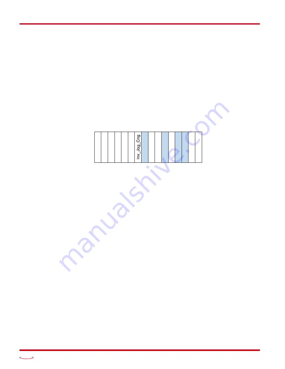
Status Word 1 Format
Figure R6.5 Command Mode: Status Word 1 Format
Bit 15: Drive_Is_Enabled –
Set to “1” when the motor driver section of the SMD23E2 or SMD24E2 is
enabled and current is available to the motor. Set to “0” when the motor driver section is disabled. If
this bit is set to “1”, the motor current remains present when an E-Stop input is active. Motor current
is removed if there is a Driver_Fault (Bit 7 below) regardless of the state of this bit. Motor current is
also removed if the motor is idle and Idle Current Reduction is programmed to its
To 0%
setting.
Bit 14: Stall_Detected –
Set to “1” when a motor stall has been detected.
Bit 13: Command_Acknowledge –
Normally “0”. This bit is set to “1” when one of the following com-
mands completes successfully:
Preset Position
Preset Encoder Position
Reset Errors
This bit resets to “0” when the command bit is reset to “0” by the host controller.
Bit 12: Absolute Encoder Error –
Only available on units with the absolute encoder, this bit is set to “1”
under the following conditions:
The shaft was subject to acceleration in excess of 160,000°/sec
2
(444.4 rev/sec
2
) while power
was removed from the unit
The internal battery is fully discharged or damaged
The unit itself is damaged
If this bit is set, cycle power to the unit. If the bit remains set, contact AMCI technical support for
assistance.
Bit 11: Heartbeat_Bit –
This bit will change state approximately every 500 milliseconds. Monitor this bit to
verify that the unit and network connection are operating correctly. Note that this bit is only available
while the unit is in Command Mode.
Status Word 1
15 14 13 12 11 10 09 08 07 06 05 04 03 02 01 00
Dri
v
e_
Enab
le
d
Sta
ll_
Det
e
c
ted
Cm
d
_
Ack
Abs_En
c_E
rr
T
e
mp_90
°C
Conn
ect
_
L
o
st
0
0
0
0
IN
2_Act
iv
e
IN
1_Act
iv
e
Dr
iv
er_F
au
lt
Li
mit
_
Cond
it
io
n
Heart
bea
t_
Bi
t
Summary of Contents for SMD23E2 Series
Page 10: ...ABOUT THIS MANUAL SMD23E2 and SMD24E2 User Manual ADVANCED MICRO CONTROLS INC 10 Notes...
Page 44: ...MOTION CONTROL SMD23E2 and SMD24E2 User Manual ADVANCED MICRO CONTROLS INC 44 Notes...
Page 54: ...CALCULATING MOVE PROFILES SMD23E2 and SMD24E2 User Manual ADVANCED MICRO CONTROLS INC 54 Notes...
Page 88: ...COMMAND MODE DATA FORMAT SMD23E2 and SMD24E2 User Manual ADVANCED MICRO CONTROLS INC 88 Notes...
Page 128: ...MODBUS TCP CONFIGURATION SMD23E2 and SMD24E2 User Manual ADVANCED MICRO CONTROLS INC 128 Notes...
Page 134: ...LEADERS IN ADVANCED CONTROL PRODUCTS ADVANCED MICRO CONTROLS INC...


