background image

20 Gear Drive, Plymouth Ind. Park, Terryville, CT 06786
Tel: (860) 585-1254  Fax: (860) 584-1973  http://www.amci.com

7

CHAPTER 1

INTRODUCTION TO THE SD17060E

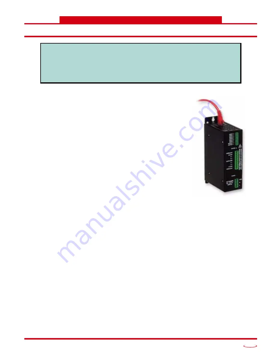
The SD17060E

The SD17060E is a 6.0Arms micro-stepping drive with a 170Vdc internal 
bus voltage.  What makes the SD17060E unique is its built-in indexer that 
accepts configuration and command data from a host system over the 
internal Ethernet port.  This combination of host and drive gives you sev-
eral advantages:

h

Sophisticated I/O processing can be performed in the host (PLC or 
other controller) before sending commands to the SD17060E

h

All motion logic is programmed in the host, eliminating the need to 
learn a separate motion control language

h

Eliminating the separate indexer lowers Total System Cost

The first protocol released for the SD17060E is Ethernet/IP, which makes 
the SD17060E easy to integrate into Allen-Bradley controller systems.

The SD17060E is powered by a nominal 120Vac 50/60Hz source.  The 
output motor current is fully programmable from 1.0Arms to 6.0Arms 
which makes the SD17060E compatible with AMCI’s complete line of 
size 23 through size 42 stepper motors.  Steps per Turn, Idle Current 
Reduction, Current Loop Gain, and Anti-Resonance Circuit are also fully 
programmable.  If you have used other stepper indexer products from 
AMCI you will find programming to be very similar to these products.

In addition to power and motor hookups, the SD17060E has three DC inputs and one DC output that are used 
by the indexer.  Configuration data from the host sets the function of these points.  The output can be config-
ured to be a Fault Output or a general purpose output.  Each input can be individually configured as a:

h

CW Limit Switch

h

CCW Limit Switch

h

Home Limit Switch

h

Capture Position Input to optionally stops a manual jog

h

Emergency Stop Input

In addition to these functions, the inputs can be programmed to accept a quadrature encoder with marker 
pulse.  An encoder input gives you the ability to:

h

Home the machine to the encoder marker pulse

h

Make absolute and relative moves based on the encoder count instead of the stepper pulse count.  

h

Detect motor stall conditions.

An encoder input also allows you to drive the motor through a feature called Electronic Gearing.  In this 
mode, the stepper motor follows the rotation of an external encoder.  This encoder is typically attached to 
another motor.  The ratio of encoder pulses to stepper pulses is programmable over a wide range.  This mode 
electronically couples the two motors together through a programmable gear ratio.

This manual is designed to get you up and running quickly using the SD17060E stepper drive.
As such, it assumes you have some basic knowledge of stepper systems, such as the resolution
you want run your motor at, and the reasons why you’d want to use Idle Current Reduction and
the reasons why you wouldn’t.  If these terms or ideas are new to you, we’re here to help.  AMCI
has a lot of information on our website and we are adding more all the time.  If you can’t find what
you’re looking for at http:///www.amci.com, send us an e-mail or call us.  We’re here to back you
up with all of our knowledge and experience.

Summary of Contents for SD17060E

Page 1: ...SD17060E Ethernet IP Stepper Motor Indexer Drive A M CI Motion Contro l P r o d u c t s ADVANCED MICRO CONTROLS INC U s e r M anual Manual 940 0S090...

Page 2: ...shall at its option repair or replace free of charge any equipment covered by this warranty which is returned shipping charges prepaid within eighteen months from date of invoice and which upon examin...

Page 3: ...der Position Input 13 Defining Home Position 13 Position Preset Command 13 Find Home CW Find Home CCW Commands 13 Chapter 2 Motion Control cont d Manual Relative and Absolute Moves 16 Manual Moves 16...

Page 4: ...bling Bootp Protocol 43 Setting the IP Address 43 Disabling the Bootp Protocol 43 Testing the New IP Address 43 Chapter 6 Host Configuration RSLogix 5000 Configuration 45 Configure Bridge Module As Ne...

Page 5: ...ed to prevent changes to the document You are allowed to select and copy sections for use in other documents and if you own Adobe Acrobat version 4 05 or later you are allowed to add notes and annotat...

Page 6: ...s detailed information on how the drive can be used to control motion in your application 3 GENERAL INSTALLATION GUIDELINES Anyone new to installing electronic controls in an industrial environ ment T...

Page 7: ...he indexer Configuration data from the host sets the function of these points The output can be config ured to be a Fault Output or a general purpose output Each input can be individually configured a...

Page 8: ...own location to another known location Blend Move Allows you to perform a sequence of relative moves without stopping between each one Hold Move Allows you to suspend a move and restart it without los...

Page 9: ...r board This LED will briefly flash red on power up while the SD17060E is initializing It will be green and on steady when the Ethernet daughter board and the rest of the SD17060E are communicating co...

Page 10: ...n 0 2 Amp steps Resolution Programmable to any value from 200 to 32 767 steps per revolution Idle Current Reduction Programmable from 0 to 100 programmed motor current in 1 increments Motor cur rent i...

Page 11: ...arameter has an effect on the actual rotational speed of the shaft If you program the Steps per Turn to 500 and perform a move with a Programmed Speed of 5 000 steps per second the shaft will rotate a...

Page 12: ...speed Available Inputs The SD17060E has three DC inputs that accept 3 5 to 27Vdc signals 5 to 24Vdc nominal They can be wired as differential sinking or sourcing inputs How the SD17060E uses these inp...

Page 13: ...Z pulse from the encoder The SD17060E only uses the Z pulse when homing the position as described below Capture Encoder Position Input When Inputs 1 and 2 are configured to act as encoder inputs Input...

Page 14: ...wait 2 seconds 7 Return to the Home Input at the programmed Starting Speed Stop when the Home Input transitions from Inactive to Active Overtravel Limit Activates During Homing Profile Figure 2 5 Over...

Page 15: ...Speed Stop when Home Limit transitions from inactive to active Homing Operation When Overtravel Limit Already Active Figure 2 7 Overtravel Limit Active 1 Accelerate to the Programmed Speed in the dir...

Page 16: ...d direction as long as the command bit is active These moves can be stopped with an external switch or sensor brought directly into the SD17060E h Relative Moves The motor rotates in the programmed di...

Page 17: ...eset to 0 h A positive transition on an input configured as a Stop Manual Move and Capture Encoder Position input h You toggle the Hold Move control bit in the Network Input Data The use of the Hold M...

Page 18: ...owed by your 90 position etc Absolute Moves Before you can perform an Absolute Move you must set the machine position to a known value This is accomplished by using the Preset Position command or homi...

Page 19: ...h sup ported The figure below represents either a relative Encoder Move of 11 000 counts or an absolute Encoder Move to position 16 000 The figure shows that the encoder position you program in the mo...

Page 20: ...irst Blend Move then program the second move and run it in the opposite direction You can also run the same profile in opposite direction as shown below 4 The Programmed Speed of each segment must be...

Page 21: ...le The SD17060E will respond by setting the Blend Move Program Mode bit in the Network Input Data At the beginning of the programming cycle the SD17060E will also set the Transmit Blend Move Segment b...

Page 22: ...was in its Hold state One potential application for this ability is bringing a move to a controlled stop when your controller senses an end of stock condition The move can be put in its Hold state unt...

Page 23: ...of the encoder AMCI refers to it as Electronic Gearing because the SD17060E has four parameters that allow you to set any turns ratio you want between the encoder and the motor Encoder Pulses Per Turn...

Page 24: ...ltiplier and Divisors Two rotations of the encoder 8 192 counts 1 motor rotation Similarly you can adjust the Steps per Turn value to adjust the ratio as well This technique allows you to set a median...

Page 25: ...re is completely optional and you can leave the Current Loop Gain at its default setting of 1 for standard motor performance Assuming a stable line voltage of 115 Vac the following gains can be used f...

Page 26: ...MOTION CONTROL ADVANCED MICRO CONTROLS INC 2 26 Notes...

Page 27: ...Earth for the safe operation of the device Protection against electric shock should the device be damaged Functional Earth Connection Point that must be tied to Earth to improve noise immunity of the...

Page 28: ...ctions The American NEC allows the use of solid wire for grounding wires but this should be avoided for the same reasons they should not be used for the Grounding Electrode Conductor Avoiding Groundin...

Page 29: ...ounding electrodes and earth A similar problem exists on machines that are not properly bonded together The resistance of a poor bond in the system will result in a voltage potential across the connec...

Page 30: ...erience that nuisance faults can be caused by another system on the same feeder circuit that does not have adequate surge suppression devices System Layout Considerations The first step to achieving a...

Page 31: ...you are attaching to the supply Component Placement Once you have established the proper categories of all of the system s wires and cables and determined all of you components including surge suppres...

Page 32: ...h Like all motors stepper motors are noise generators and must be properly grounded when installed h Keep the motor wires as short as possible Consider twisting the winding pairs together to minimize...

Page 33: ...eft and right of the drive and one inch 25 mm of space in front of the drive These dimensions are typical for convectional cooling If you have an active cool ing system such as enclosure fans you will...

Page 34: ...e cable before wiring the connector When you re sure the wiring is correct slide the boot over the connector to cover the screw heads Figure 4 1 Power and Grounding Connections 1 Input power must be 9...

Page 35: ...arth ground point near it Use a minimum 8 gauge stranded wire or 1 2 wire braid as the grounding wire 2 Do not disassemble any stepper motor A significant reduction in motor performance will result Co...

Page 36: ...nector When you re sure the wiring is correct slide the boot over the connector to cover the screw heads Always remove power from the SD17060E before connecting or disconnecting the motor 1 Never conn...

Page 37: ...INTERLOCK B CTAP B B EARTH GND A CTAP INTERLOCK A A 6 LEAD MOTOR Six Lead Center Tap Connected Motor Case INTERLOCK B CTAP B B EARTH GND A CTAP INTERLOCK A A 4 LEAD MOTOR Four Lead Connected Motor Cas...

Page 38: ...m the power supply to each sensor Do Not daisy chain power from one sensor to the next GROUND THE SHIELD OF THE SENSOR CABLE 1 Ground only one end of shield 2 Shield is usually grounded where the sign...

Page 39: ...nal If used it must be wired into Input 3 The Z channel is only used when homing the SD17060E Figure 4 7 Sample Encoder Wiring SD17060B Output OUTPUT OUTPUT RLIMIT VDC 5 to 24V SD17060E Output Sinking...

Page 40: ...status LED s indicate the health of the network connection between the SD17060E and its host The Sta tus LED on the front of the unit indicates the state of the SD17060E itself h Network Status Indica...

Page 41: ...Windows XP and Vista and it may prevent your computer for communicating with the SD17060E Configuring your firewall to allow the BOOTP protocols through is beyond the scope of this manual The easiest...

Page 42: ...tead of the interface attached to the SD17060E If you have trouble connecting to the SD17060E and you have already disabled the firewall then disable all network interfaces except for the one attached...

Page 43: ...operties window again Enter the new IP address for the SD17060E and click OK 2 Apply2 power to the drive and wait for the Unit Status LED to come on solid green and the Network Status LED to be flashi...

Page 44: ...nce the terminal is open type in ping aaa bbb ccc ddd where aaa bbb ccc ddd in the new IP address of the SD17060E The computer will ping the SD17060E and the message Reply from aaa bbb ccc ddd bytes 3...

Page 45: ...1756 L1 processor is used in the screen images below 1 Insert a bridge module into the I O Configuration tree As shown in figure 6 1 on the right right click on the I O Configuration folder and selec...

Page 46: ...ow scroll down the list until you find the entry that has a description of Generic Ethernet Module Module Type is ETHERNET MODULE in figure Click on the module name to select and then click the OK but...

Page 47: ...data files h An Integer file to contain the data from the SD17060E This file must have enough elements to contain all of the data read from the drive h An Integer file to contain the data sent to the...

Page 48: ...the SD17060E enter the integer file where the source data will be located in the Data Table Address Send field and press Enter 7 Enter a value of 20 either in the Size In Bytes Receive or Size In Byte...

Page 49: ...to read data from a SD17060E Please note that the Data Table Address Receive and Size in Bytes Receive fields may be dif ferent in your application Figure 6 7 Read Message Instruction Setup Screen Th...

Page 50: ...te message instructions to your program save and down load the program to the PLC Troubleshooting If you are unable to communicate with the SD17060E the problem may be that the Ethernet port of your M...

Page 51: ...reset errors when they occur The SD17060E must be programmed with a valid configuration before it will allow you to switch to this mode Multi Word Format Many of the hosts that can be used with the S...

Page 52: ...tall detection 1 enables motor stall detection Only valid when an encoder is used and attached to the motor controlled by the SD17060E Bit 11 Home Proximity Bit Enable Bit 0 when Home Proximity bit is...

Page 53: ...til a fault occurs 1 configures Output 1 to be a general purpose output whose state is determined by a bit in the Command Mode Network Output Data This output is in an ON state when power is applied t...

Page 54: ...h the input when it is active Notes on Other Configuration Words h Information on the Multi Word Format used when programming the Starting Speed can be found on page 51 h Current Loop Gain settings fo...

Page 55: ...use an encoder Command Mode The correct format for the Network Output Data when the SD17060E is in Command Mode is shown in the two tables below The first table shows the data format for most commands...

Page 56: ...rting on page 21 Bit 10 Clear Errors When set to 1 the SD17060E will clear all existing errors and attempt to use the present data to run a new command Bit 9 Preset Motor Position Bit When set to 1 th...

Page 57: ...be found in the Controlling Moves In Progress section of this manual starting on page 22 Bit 1 Relative Move Bit Set to 1 to perform a Relative Move using the data in the rest of the Com mand Data A...

Page 58: ...Current Key0 See description below Description of Motor Current Keys It is possible to change the motor current on the fly while in Command Mode To do this place the new motor current in Word 8 and se...

Page 59: ...valid Bit 1 when h The motor position has not been preset h The machine has not been homed h The Network Connection has been lost and re established h An Immediate or Emergency Stop has occurred h An...

Page 60: ...et if an End Limit Switch is reached during a move This bit will be reset when the Limit Switch changes from its active to inactive state or when a Reset Errors Command is issued Bit 9 Invalid Paramet...

Page 61: ...er Position Data These two inputs words report the encoder position based on the quadrature pulses received by the SD17060E The range for the encoder position value is 32 768 000 to 32 767 999 The dat...

Page 62: ...VANCED CONTROL PRODUCTS ADVANCED MICRO CONTROLS INC ADVANCED MICRO CONTROLS INC ADVANCED MICRO CONTROLS INC ADVANCED MICRO CONTROLS INC 20 GEAR DRIVE TERRYVILLE CT 06786 T 860 585 1254 F 860 584 1973...

Reviews: