


AMC-UTx-M-xx-400 Series Digital Transmitter
17
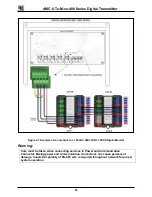
3.3 REAR LID OVERVIEW
Figure 3-2: Front Lid Rear View
8. BusPower Connectors:
The two 12 pin connectors on the BusPower Module provide
all interfaces to the UTx-M-xx-400.
9. Sensor Module Connections:
Connectors on the Sensor Module(s) are used to connect
between Sensor Modules and between Sensor Module 1
and the Transmitter
10. EOL LED
This LED will be illuminated Green if the UTx is configured
as EOL
10
EOL LED
8
BusPower
Connectors
9
Sensor Module
Connections


