AMC-UTx-M-xx-400 Series Digital Transmitter
16
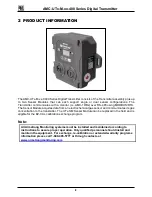
1. Enclosure:
Enclosure and Lid Assembly, PC-ABS blend, 5.45
” length
by 6.14” width Wall mount with two mount points. Option for
Pole Mount.
2. Digital Display:
Displays gas concentration & Status information
3. Network Status LED:
Indicates status of Network Interface and will show whether
or not the UTx has established / maintained Network
Communication
4. Sensor Status LED:
The Sensor Status LED will show the same error code that
is being communicated by the Sensor Module(s) or display
the highest priority error (if multiple errors codes are being
communicated to it by the Sensor Module(s)
5. Sensor Module Opening:
This inlet allows target gas to flow into the sensor. The inlet
is also used for gas calibration.
6. Sensor Module LED:
Sensor Module LEDs will show the status of the sensor
element within the Sensor Module, or the status of the
Sensor Module itself
7. Menu Buttons:
Momentary Pushbuttons for user Interface.


