Amazone KE 2500 Special Operating Instruction Download Page 150


Cleaning, maintenance and repair 


150


KG / KX / KE  BAH0063-6  04.16


12.3.2 

Repositioning/replacing the gear wheels  
on the WHG/KX / WHG/KG Special / Super (specialised workshop) 


When the gearbox cover is opened, transmission fluid runs out.  

To prevent contamination from escaping fluid,  


raise the mounted implement using the tractor's three-point 
hydraulics until the implement is inclined about 30° forwards 


park the implement on solid ground and reduce the oil level by 
draining off the transmission fluid.  
Only reuse the collected transmission fluid if it has not been 
contaminated by dirt particles. 


DANGER 

Secure the raised soil tillage implement which is attached to the 
tractor against unintentional lowering by using suitable support 
elements or a crane. 

12.3.2.1  Repositioning/replacing the gear wheels on the WHG/KX 

  1.  Couple the soil tillage implement to the 

tractor. 

  2.  Uncouple the seed drill. 

  3.  Tilt the implement about 30° forwards using 

the tractor's three-point hydraulic system. 

  4.  Switch off the tractor PTO shaft, apply the 

tractor parking brake, switch the tractor 
engine off and remove the ignition key. 

  5.  Secure the raised implement using suitable 

support elements or a crane. 

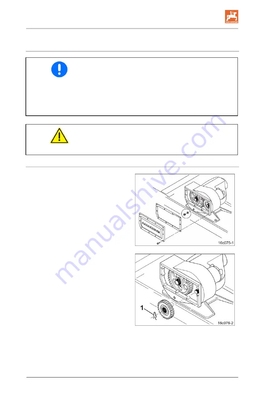
  6.  Open the gearbox cover. 


Fig. 157


  7.  Remove the retaining springs (Fig. 157/1). 

  8.  Remove the gear wheels and, using the 

speed table,  


swap them around or  


replace with a different set of gear 
wheels. 

  9.  Fit the retaining springs. 

 10.  Close the gearbox cover and cover gasket. 

 11.  Lower the implement.  
 12.  Check the gearbox for leak points. 

 13.  Check the oil level. 


Fig. 158


Summary of Contents for KE 2500 Special

Page 1: ...llage implements Rotary cultivator KG Special KG Super Rotary cultivator KX Rotary harrow KE Special KE Super MG4321 BAH0063 6 04 16 Please read this operating manual before initial operation Keep it...

Page 2: ...person concerned would not only harm himself but also make the mistake of blaming the machine for the reason of a possible failure instead of himself In order to ensure a good success one should go in...

Page 3: ...cturer s address AMAZONEN WERKE H DREYER GmbH Co KG Postfach 51 D 49202 Tel Fax E mail Hasbergen Germany 49 0 5405 501 0 49 0 5405 501 234 amazone amazone de Spare part orders Spare parts lists are fr...

Page 4: ...d Damage can only be rectified if problems are signalled immediately Before initial operation read and observe this operating manual and particularly the safety information Only after careful reading...

Page 5: ...s working 25 2 16 Safety information for users 26 2 16 1 General safety instructions and accident prevention instructions 26 2 16 2 Mounted implements 30 2 16 3 Hydraulic system 31 2 16 4 Electrical s...

Page 6: ...6 5 17 Working with an AMAZONE mounted seed drill 87 5 17 1 Coupling parts optional 87 5 17 2 Lifting frame optional 87 5 17 3 Lift height limiter optional 89 5 17 4 Side stabiliser for lifting frame...

Page 7: ...djusting the tractor wheel mark eradicator optional 126 8 3 1 Exceeding the maximum working depth 127 8 4 Adjusting the cutting rail optional only with cracker disc roller 129 8 5 Adjusting the levell...

Page 8: ...ication points overview 157 12 7 Maintenance schedule overview 159 12 8 WHG KE Special gearbox and WHG KE Super gearbox 161 12 8 1 Ventilation 161 12 8 2 Check the oil level 161 12 8 3 Changing transm...

Page 9: ...ating manual All the directions specified in the operating manual are always seen in the direction of travel 1 3 Diagrams Instructions and responses Activities to be carried out by the user are given...

Page 10: ...e state to replace damaged warning symbols If you still have queries please contact the manufacturer Obligations of the user Before starting work anyone charged with working with on the implement is o...

Page 11: ...ese shall be available to the operator at the latest on conclusion of the contract Guarantee and liability claims for damage to people or property will be excluded if they can be traced back to one or...

Page 12: ...eath or serious physical injury WARNING Indicates a medium risk which could result in death or serious physical injury if not avoided If the instructions are not followed then this may result in death...

Page 13: ...personnel Check all the available safety equipment regularly 2 4 Safety and protective equipment Before starting up the implement each time all the safety and protection equipment must be properly att...

Page 14: ...2 Instructed persons are those who have been instructed in their assigned tasks and in the possible risks in the case of improper behaviour have been trained if necessary and have been informed about...

Page 15: ...electronic energy on the implement Use appropriate measures to inform the operating personnel You can find detailed information in the relevant sections of this operating manual 2 9 Maintenance and re...

Page 16: ...type approval for example remains valid in accordance with national and international regulations Vehicles with an official type approval or with equipment connected to a vehicle with a valid type app...

Page 17: ...ar and spare parts from third parties there is no guarantee that they have been designed and manufactured in such a way as to meet the requirements placed on them AMAZONEN WERKE shall accept no liabil...

Page 18: ...ning symbol consists of two fields Field 1 is a symbol describing the danger surrounded by triangular safety symbol Field 2 is a symbol showing how to avoid the danger Warning symbols explanation The...

Page 19: ...ndstill before reaching into the danger area MD 076 Risk of drawing in entrapment for hand or arm due to moving force transmission parts This hazard can cause the most severe injuries with loss of bod...

Page 20: ...2 Risk of falling when riding the implement on treads or platforms Causes serious potentially fatal injuries anywhere on the body It is forbidden to ride on the implement or climb the implement when i...

Page 21: ...pended loads or raised implement parts MD 095 Read and follow the operating manual and safety information before starting up the implement MD 096 Danger from escaping high pressure hydraulic fluid due...

Page 22: ...aulic system only from the designated workstation under no circumstances if you are in the lifting area between the tractor and implement MD 102 Danger from intervention in the implement e g installat...

Page 23: ...ns for cleaning servicing and maintaining in the appropriate chapter of the operating manual MD 119 This symbol indicates the maximum drive speed 1000 rpm and direction of rotation of the drive shaft...

Page 24: ...General Safety Instructions 24 KG KX KE BAH0063 6 04 16 2 13 1 Positions of warning symbols and other labels Fig 1 KX 3000 Fig 2 WHG KE Special Super Fig 3 WHG KX Fig 4 WHG KG Special Super...

Page 25: ...ecured working areas Failure of important machine functions Failure of prescribed methods of maintenance and repair Danger to people through mechanical and chemical impacts Risk to the environment thr...

Page 26: ...traffic visibility and weather conditions the driving characteristics of the tractor and the connected or coupled implement Coupling and uncoupling the implement Only connect and transport the implem...

Page 27: ...actor or uncoupling it from the tractor There are nip and shear points in the area of the coupling point between the tractor and the implement It is forbidden to stand between the tractor and the impl...

Page 28: ...the implement Secure the tractor against unintentional start up and rolling before you leave the tractor For this Lower the implement onto the ground Apply the parking brake Switch off the tractor en...

Page 29: ...cure all the swivel implement parts in the transport position against risky position changes Use the transport locks intended for this Before transporting lock the operating lever of the tractor s thr...

Page 30: ...port devices When mounting implements at the front or rear of a tractor do not exceed The permissible total tractor weight The permissible tractor axle loads The approved load capacities of the tracto...

Page 31: ...move the ignition key Have the hydraulic hose lines checked for proper functioning by a specialist at least once a year Replace the hydraulic hose lines if they are damaged or worn Use only genuine AM...

Page 32: ...ing whether the installation might cause faults on the vehicle electronics or other components Ensure that the retrofitted electrical and electronic components comply with the EMC Directive in the app...

Page 33: ...rs or it is not needed WARNING After the PTO shaft is switched off there is a danger of injury from the continued rotation of freewheeling implement parts Do not approach the implement too closely dur...

Page 34: ...hem as necessary Secure the raised implement and or raised implement parts against unintentional lowering before performing any cleaning maintenance or repair work on the implement When replacing work...

Page 35: ...lement Fig 5 DANGER Only attach the lifting gear at the marked location Do not stand under suspended loads Loading the implement on a transport vehicle 1 Uncouple the seed drill and deep loosener from...

Page 36: ...ual modules and controls If possible read this section when actually at the implement This helps you to understand the implement better 4 1 Overview of assembly groups Fig 7 KX 3000 1 Lower link coupl...

Page 37: ...d protective equipment Fig 8 Universal joint shaft guard Fig 8 Fig 9 1 Tool guard plate 2 Levelling board 3 Side panel 4 Roller trailing The above mentioned components serve as tool protection use of...

Page 38: ...ive hydraulic function to the pressure line of a tractor control unit Fig 10 The function of the tractor control unit is represented symbolically Latched for a permanent oil circulation When the butto...

Page 39: ...gns Fig 11 Fig 12 1 2 rear facing turn indicators 2 2 reflectors yellow 3 2 brake and rear lights 4 2 red reflectors Fig 12 Fig 13 1 2 forwards facing warning signs 2 2 forwards facing limiting lights...

Page 40: ...mplement is part of a sowing combination Slopes can be travelled Along the contours Direction of travel to the left 15 Direction of travel to the right 15 Along the gradient Up the slope 15 Down the s...

Page 41: ...ns Here the special safety regulations of the appropriate section shall be valid No one may stand in the implement danger area as long as the tractor engine is running with the universal joint shaft h...

Page 42: ...he stipulations of the valid EU directives The rating plate shows Implement ID No Type Model year Factory Basic weight kg Fig 14 4 8 Noise production data The workplace related emission value acoustic...

Page 43: ...w Number of rotors 8 Tool tines see below Working depth max cm 20 Data for the calculation of tractor weights and tractor axle loads Basic weight KE 2500 Special KG 795 Roller SW 2500 420 KG 198 PW 25...

Page 44: ...0 Data for the calculation of tractor weights and tractor axle loads Basic weight KE 3000 Special KG 850 Roller SW 3000 420 KG 227 SW 3000 520 KG 250 PW 3000 420 KG 303 PW 3000 500 KG 376 PW 3000 600...

Page 45: ...20 Data for the calculation of tractor weights and tractor axle loads Basic weight KE 3000 Super KG 860 Roller SW 3000 420 KG 227 SW 3000 520 KG 250 PW 3000 420 KG 303 PW 3000 500 KG 376 PW 3000 600 K...

Page 46: ...ights and tractor axle loads Basic weight KE 3500 Super KG 1360 Roller SW 3500 520 KG 290 PW 3500 500 KG 435 PW 3500 600 KG 706 KW 3500 580 125 KG 660 KW 3500 580 166 KG 610 CDW 3500 550 125 KG 829 2...

Page 47: ...see below Working depth max cm 20 Data for the calculation of tractor weights and tractor axle loads Basic weight KE 4000 Super KG 1180 Roller SW 4000 520 KG 320 PW 4000 500 KG 496 PW 4000 600 KG 809...

Page 48: ...ow Working depth max cm 20 Data for the calculation of tractor weights and tractor axle loads Basic weight KX 3000 KG 1175 Roller SW 3000 520 KG 250 PW 3000 500 KG 376 PW 3000 600 KG 607 KW 3000 520 1...

Page 49: ...orking depth max cm 20 Data for the calculation of tractor weights and tractor axle loads Basic weight KG 3000 Special KG 1200 Roller SW 3000 520 KG 250 PW 3000 500 KG 376 PW 3000 600 KG 607 KW 3000 5...

Page 50: ...ghts and tractor axle loads Basic weight KG 3500 Special KG 1330 Roller SW 3500 520 KG 290 PW 3500 500 KG 435 PW 3500 600 KG 706 KW 3500 580 125 KG 660 KW 3500 580 166 KG 610 CDW 3500 550 125 KG 829 2...

Page 51: ...see below Working depth max cm 20 Data for the calculation of tractor weights and tractor axle loads Basic weight KG 4000 Special KG 1500 Roller SW 4000 520 KG 320 PW 4000 500 KG 496 PW 4000 600 KG 8...

Page 52: ...Working depth max cm 20 Data for the calculation of tractor weights and tractor axle loads Basic weight KG 3000 Super KG 1250 Roller SW 3000 520 KG 250 PW 3000 500 KG 376 PW 3000 600 KG 607 KW 3000 52...

Page 53: ...ights and tractor axle loads Basic weight KG 3500 Super KG 1360 Roller SW 3500 520 KG 290 PW 3500 500 KG 435 PW 3500 600 KG 706 KW 3500 580 125 KG 660 KW 3500 580 166 KG 610 CDW 3500 550 125 KG 829 2...

Page 54: ...s see below Working depth max cm 20 Data for the calculation of tractor weights and tractor axle loads Basic weight KG 4000 Super KG 1500 Roller SW 4000 520 KG 320 PW 4000 500 KG 496 PW 4000 600 KG 80...

Page 55: ...000 Special from 66 kW 90 HP to 162 kW 220 HP KG 3500 Special from 77 kW 105 HP to 162 kW 220 HP KG 4000 Special from 88 kW 120 HP to 162 kW 220 HP KG 3000 Super from 66 kW 90 HP to 220 kW 300 HP KG 3...

Page 56: ...oil Gear oil CLP CKC 460 DIN 51517 Part 3 ISO 12925 Oils that comply with this standard can be topped up or used to replace the existing oil in the spur gear trough Only fill with new and clean gear o...

Page 57: ...3000 Special 25 litres KE 3000 Super 25 litres KE 3500 Super 30 litres KE 4000 Super 35 litres KX 3000 25 litres KG 3000 Special Super 25 litres KG 3500 Special Super 30 litres KG 4000 Special Super 3...

Page 58: ...tor KG Rotary harrows have on grip tool tines For seed bed preparation Without pre tilling mulch sowing Straw and other organic matter is mulched close to the surface After chisel cultivators or deep...

Page 59: ...Layout and function KG KX KE BAH0063 6 04 16 59 5 1 KE rotary harrows KE 3000 Special rotary harrow with lifting frame Fig 16 KE 3000 Super rotary harrow Fig 17...

Page 60: ...Layout and function 60 KG KX KE BAH0063 6 04 16 5 2 KX rotary cultivator KG rotary cultivator KX 3000 rotary cultivator Fig 18 KG 3000 Special rotary cultivator with lifting frame Fig 19...

Page 61: ...function KG KX KE BAH0063 6 04 16 61 KG 3000 Super rotary cultivator Fig 20 5 3 Threaded cartridge The threaded cartridge Fig 21 1 contains the operating manual the ratchet to operate the levelling bo...

Page 62: ...If a cat 2 upper link is to be connected to the cat 3 upper link pin Fig 22 2 the holes must be retrofitted in a specialist workshop with two elastic bushings see online spare parts list With the exp...

Page 63: ...actor and implement The three point extension consists of 3 spacers Each spacer is pegged to the implement using 2 pins and secured using linch pins 5 5 1 Three point hitch extension for KE rotary har...

Page 64: ...ultivators Fig 25 Three point extension for KX KG rotary cultivators Fig 25 Part name Pin diameter mm Attachment category Number 1 Upper link extension 1 2 Upper link pin 25 Cat 2 1 3 Upper link pin 3...

Page 65: ...6 Three point extension for KX KG rotary cultivators Fig 26 Part name Pin diameter mm Attachment category Number 1 Upper link extension 1 2 Upper link pin 25 Cat 2 1 3 Upper link pin 31 7 Cat 3 2 4 Lo...

Page 66: ...s The attachment frame Fig 27 1 serves to attach the horizontally and vertically adjustable tractor wheel mark eradicators Fig 27 Fig 28 Wheel mark eradicator rigid Fig 29 Wheel mark eradicator spring...

Page 67: ...00 Special KG 3000 Super KG 4000 Super Cage roller SW 2500 420 SW 3000 420 SW 3000 520 SW 3000 520 SW 3500 520 SW 4000 520 Tooth packer roller PW 2500 420 PW 3000 420 PW 2500 500 PW 3000 500 PW 3000 5...

Page 68: ...hod The tooth packer roller compacts the soil uniformly over the entire working width Cleaning Adjustable carbide coated scrapers clean the roller Fig 32 5 7 3 Wedge ring roller KW KW520 KW580 Field o...

Page 69: ...ded in the compacted soil The integrated cross bars of the steel packer rings provide additional traction for the roller The cracker disc roller has a spring suspended cutting rail Fig 34 2 Fig 34 Two...

Page 70: ...xed obstacle the tool carriers may come to a stop To prevent damage to the gearbox the implement is equipped with an overload clutch The overload clutch is located on the input shaft of the implement...

Page 71: ...overload clutch The gearbox type depends on the machine type and the permissible tractor engine power see table Do not couple the implement with tractors which exceed the permissible tractor engine po...

Page 72: ...oxes are fitted with a PTO shaft through drive The speed at the PTO shaft through drive corresponds to the tractor s PTO shaft speed Fig 38 WHG KE Super Speed table for WHG KE Special 1 Gear wheel pai...

Page 73: ...gearbox is fitted with the following as standard Gear wheel I 22 teeth Gear wheel II 25 teeth 2 Tine speed rpm for Tractor PTO shaft speed 1000 rpm Tractor PTO shaft speed 750 rpm Tractor PTO shaft sp...

Page 74: ...speeds Fig 39 WHG KX Speed table WHG KX 1 Gear wheel pairing The gearbox is fitted with the following as standard Gear wheel I 29 teeth Gear wheel II 36 teeth 2 Tine speed rpm at Tractor PTO shaft spe...

Page 75: ...standard Gear wheel I 21 teeth Gear wheel II 23 teeth 2 Tine speed rpm at Tractor PTO shaft speed 1000 rpm Tractor PTO shaft speed 750 rpm Tractor PTO shaft speed 540 rpm Example Gear wheel pairing I...

Page 76: ...haft Order number Rotary harrow KE 3000 Super KE 3500 Super KE 4000 Super Bondioli Pavesi SFT H7 Universal joint shaft with ratchet clutch 1 3 8 inch 6 parts 760 mm EJ578 Bondioli Pavesi SFT H7 Univer...

Page 77: ...1 3 4 inch 6 parts 760 mm EJ659 Soil tillage implement Universal joint shaft Order number Rotary cultivator KG 3000 Super KG 3500 Super KG 4000 Super Bondioli Pavesi SFT S8 Universal joint shaft with...

Page 78: ...ed The KG Super rotary cultivator can be equipped with the electronic drive monitor If the tool carriers come to a stop the on board computer issues an alarm via the display on the control terminal Fi...

Page 79: ...uper KE 3500 Super KE 4000 Super KE drag Special 26 cm Rotary cultivator KX 3000 KG drag 33 cm KG grip Special 33 cm Potato tines 40 cm Rotary cultivator KG 3000 Special KG 3500 Special KG 4000 Specia...

Page 80: ...ag Special anticlockwise Tool tines KG drag anticlockwise Fig 45 Fig 46 Tool tines KG grip Special HD anticlockwise Tool tines KG grip Super anticlockwise Fig 47 Fig 48 Tool tines KG grip Special HD a...

Page 81: ...t great working depths in order to prevent damage wear to the tool carriers If the tines fall below the minimum length prescribed by the manufacturer claims due to rock damage shall not be accepted Fi...

Page 82: ...f the working depth is attained by turning the depth setting pin in the same square hole The edges Fig 54 1 of the depth setting pins have different distances and are labelled with the numbers 1 to 4...

Page 83: ...the spring tension must be adjusted to the soil conditions The side panel is fastened with two bolts and can be adjusted in height Fig 56 Soil tillage implement Side panel Rotary harrow KE 2500 Speci...

Page 84: ...position The adjustable tension of the spring is adjusted at the factory for light and medium soils Adjust the spring tension as follows Increase it on heavy soils Decrease it when incorporating stra...

Page 85: ...he scale next to the spindle as a guide For conventional drilling adjust the working height of the levelling bar so that a small earth wall is always pushed in front to level existing undulations For...

Page 86: ...MAZONE implements The soil tillage implement can be combined with Mounted seed drill Fig 63 Pack top seed drill mechanical Fig 64 Pack top seed drill pneumatic Fig 65 Deep loosener Fig 65 This operati...

Page 87: ...the combination of soil tillage implement roller and mounted seed drill with the coupling parts the lifting power requirement can be reduced using the lifting frame The lifting frame first lifts the...

Page 88: ...running Once the seed drill has been raised the tractor lower links should raise the implement combination only to the point where the tines of the soil tillage implement and the roller are just out...

Page 89: ...itch off the PTO shaft and the associated loss of pressure in the precision airplanter If the seed drill is raised by the lifting frame the top link Fig 71 1 pulls up the activation hook Fig 71 2 and...

Page 90: ...the universal joint shaft from being mounted on the PTO shaft stub The PTO shaft is connected via the roller frame by means of a shaft mounted gearbox Fig 73 There are two gearboxes available each wit...

Page 91: ...r driver as an orientation aid The tractor driver drives over the centre of the mark The track markers are attached to the cultivator Fig 75 It is possible to set the length of the track marker the wo...

Page 92: ...h crop seeding unit enables the seeding of fine seeds and catch crops during soil cultivation 1 Blower fan with electric drive 2 Foldable ascent 3 Automatic locking of the foldable ascent Also see the...

Page 93: ...on Use of the implement Only couple and transport the implement to with a tractor which is suitable for the task The tractor and implement must meet the national road traffic regulations The operator...

Page 94: ...the required braking delay with the implement connected Requirements for the suitability of a tractor are in particular The permissible total weight The permissible axle loads The permissible drawbar...

Page 95: ...awbar load of the hitched implement This notice applies only to Germany If having tried all possible alternatives it is not possible to comply with the axle loads and or the permissible total weight t...

Page 96: ...r and front implement mounting or front weight or measurement a1 m Distance from the centre of the front axle to the centre of the lower link connection See tractor operating manual or measurement a2...

Page 97: ...he tractor operating manual in the following table 6 1 1 4 Calculation of the actual total weight of the combined tractor and implement H L V tat G T G G Enter the numeric value for the calculated act...

Page 98: ...and insufficient tractor steering and brake power It is forbidden to couple the implement to the tractor used as the basis for calculation if one of the actual calculated values is greater than the ap...

Page 99: ...ooting cleaning maintenance and repairs while the implement is being driven as long as the tractor engine is running with the PTO shaft hydraulic system connected if the ignition key is inserted in th...

Page 100: ...side panel from the outside The reverse would cause the permissible transport width of 3 00 m to be exceeded This applies accordingly for 3 50 m and 4 00 m implements 6 4 Attaching the protective pane...

Page 101: ...rk eradicator Fig 80 4 right at the top with the positioning pin Fig 80 3 and secure with a linch pin The working depth adjustment is carried out on the field Fig 80 6 6 Attaching the roller specialis...

Page 102: ...ble hole above the carrying arm and secure the depth setting pin using a linch pin Fig 83 6 6 Fasten the second carrying arm to the second adjuster segment as described above Fig 83 Fixing the carryin...

Page 103: ...wo universal joint shaft halves to the tractor PTO shaft and the gearbox input shaft Do not interconnect the universal joint shaft halves Observe the operating manual from the universal joint shaft ma...

Page 104: ...ig 85 2 to the soil tillage implement with two pins Fig 85 3 3 Secure the pins with screws Fig 85 4 and nuts 4 Secure the chains Fig 85 5 together with the upper link Fig 85 6 to the soil tillage impl...

Page 105: ...ne of the lifting frame to the hydraulics for the tractor lower links brings advantages When actuating the tractor lower link first the seed drill is raised over the roller This reduces the required l...

Page 106: ...ting frame at the lower pivot points Secure the pin Fig 87 1 with a screw Fig 87 2 and nut 6 Position the upper link with a pin Fig 87 3 and secure with a linch pin 7 Connect the hydraulic lines to th...

Page 107: ...e implement using two implement bolts Fig 88 2 with washers Fig 88 3 4 bolts Fig 88 4 with 4 spacer sleeves Fig 88 5 6 Position the upper link Fig 88 6 with a pin Fig 88 7 and secure with a linch pin...

Page 108: ...onnect the hydraulic hose line from the mounted T connector Fig 89 5 7 Screw on the pre assembled valve holder Fig 89 1 8 Connect the hydraulic hoses to the new T connector on the valve Fig 89 5 9 Att...

Page 109: ...fluids Do not mix any mineral oils with biological oils The maximum operating pressure of the hydraulic system is 210 bar Fig 90 1 Clean the hydraulic connector and hydraulic socket of the tractor con...

Page 110: ...10 KG KX KE BAH0063 6 04 16 6 10 1 1 On lifting frame Fig 92 1 Couple the supply line for the hydraulic hose lines Fig 92 6 10 1 2 On soil tillage implement Fig 93 1 Couple the supply line for the tra...

Page 111: ...11 Uncoupling the hydraulic hose lines 1 Put the tractor control valve into the float position neutral position 2 Unlock the hydraulic connector 3 Push on the dust protection caps Fig 94 4 Place the...

Page 112: ...t shaft supplied by the universal joint shaft manufacturer Correct use and maintenance of the universal joint shaft prevents serious accidents When coupling the universal joint shaft observe the opera...

Page 113: ...ly use the upper and lower link pins provided for coupling the implement Check the upper and lower link pins for visible defects whenever the implement is coupled Replace the upper and lower link pins...

Page 114: ...implement side universal joint shaft half to the overload clutch on the gearbox input shaft and secure Observe the operating manual from the universal joint shaft manufacturer 4 Interconnect the two...

Page 115: ...h pin Fig 99 1 13 Instruct persons to get out of the danger area between the tractor and the implement 14 Engage the lower hinging points Fig 100 1 of the implement using the tractor lower links The l...

Page 116: ...heel mark eradicators all the way at the top 3 Apply the tractor parking brake switch the tractor engine off and remove the ignition key 4 Release the upper link by adjusting the upper link length 5 D...

Page 117: ...e Fig 102 2 Fig 102 Screw the catch hooks to the coupling parts so that the seed drill can be connected without problem runs closely behind the roller The closer the seed drill is attached to the roll...

Page 118: ...op pivot point Cat II of the seed drill 9 Secure the pin with a linch pin 10 Align the seed drill so that it is straight by lengthening or shortening the upper link Secure the position of the upper li...

Page 119: ...to the lifting frame using two screws for each one Fig 107 2 Fig 107 Lifting frame 2 1 has two groups of holes to which the catch hooks may be screwed The required group of holes depends on the rolle...

Page 120: ...off and remove the ignition key 7 Swivel the locking straps Fig 108 1 and secure each with a pin Fig 108 2 Secure the pins with linch pins 8 Position the top link Fig 109 1 to the top pivot point Cat...

Page 121: ...frame Fig 111 1 to the KE 3000 with the threaded pins Fig 111 2 KE 3500 and KE 4000 with the Cat II III lower link pins Fig 111 3 3 Couple the tractor with the front mounting frame 4 Screw the middle...

Page 122: ...switched off The ignition key is removed WARNING Danger of crushing shearing cutting being caught or drawn in winding and knocks through unintentional lowering of the implement raised using the tract...

Page 123: ...ig 113 1 2 Switch off the tractor PTO shaft apply the tractor parking brake switch the tractor engine off and remove the ignition key Wait until the tool carriers have come to a complete stop Fig 113...

Page 124: ...m the implement 6 Lower the soil tillage implement The carrying arms Fig 116 1 are supported by the depth setting pins Fig 116 2 7 Check that both carrying arms Fig 116 1 are resting on depth setting...

Page 125: ...hydraulic cylinders Fig 55 1 are connected to the tractor control unit Beige for adjusting the working depth The scale Fig 55 2 displays the set working depth Fig 118 Actuation of the control unit Be...

Page 126: ...e screws Fig 120 1 Fig 120 Vertical adjustment Adjust the tractor wheel mark eradicator vertically to the desired position The recessed grip Fig 121 1 serves to safely adjust the working depth Fig 121...

Page 127: ...rk results after each adjustment 8 3 1 Exceeding the maximum working depth If increasing wear of the tool tines on the soil tillage implement causes the maximum working depth to be exceeded Fig 124 2...

Page 128: ...ket Fig 127 1 6 Turn the tractor wheel mark eradicator bracket upwards Fig 127 2 7 Tighten the fastening bolts for the tractor wheel mark eradicator bracket Fig 127 1 Fig 127 8 Insert the tractor whee...

Page 129: ...tting rail and the blades Position B Repositioning of the bolt from hole Fig 132 4 to hole Fig 132 3 or Fig 132 5 causes only the net weight of the cutting rail to act on the blades The spring force o...

Page 130: ...ard 1 Adjust the spindle of the levelling board using the ratchet Fig 133 1 In the parking position the ratchet is stowed in the threaded cartridge Fig 133 2 Position the spindle with a mandrel Fig 13...

Page 131: ...rame is fully raised and locked 4 Release the Fig 136 1 cord The locking hook Fig 136 3 forms the mechanical locking mechanism of the lifting frame Unlocking the lifting frame 1 Instruct any people in...

Page 132: ...e table Fig 139 4 Turn the track marker disc to adjust the working intensity of the track marker so that it runs roughly parallel to the direction of travel on light soils and is set more to grip on h...

Page 133: ...haft of the tractor immediately if the lifted implement makes a lot of noise while running The lift height limiter can be adjusted 1 Unscrew the nuts Fig 140 1 2 Put the actuation hooks into the desir...

Page 134: ...rt vehicle The vehicle keeper and driver are responsible for compliance with the statutory stipulations The maximum permitted speed1 is 25 km h for tractors with attached soil tillage implement traili...

Page 135: ...d traffic visibility and weather conditions the driving characteristics of the tractor and the connected or coupled implement It is forbidden to ride on the implement as a passenger and or to climb on...

Page 136: ...tor control unit yellow until the track markers are fully raised 7 Check whether the track markers are locked see section Moving the track marker to transport position page 144 8 Raise the soil tillag...

Page 137: ...tor and driven implement is fully guarded i e The tractor must be equipped with a shield and the implement must be equipped with the standard universal joint shaft guard Whenever the implement is used...

Page 138: ...k and forth When turning corners take into consideration the wide sweep and the centrifugal mass of the implement Drive in such a way that you always have full control over the tractor with the attach...

Page 139: ...ment Excessive bending of the driven universal joint shaft causes increased premature wear to or immediate destruction of the universal joint shaft Switch off the PTO shaft of the tractor immediately...

Page 140: ...he prescribed speed 3 Start up the tractor and fully lower the soil tillage implement Fig 144 A tractor PTO shaft speed of 1000 rpm is recommended Setting a lower PTO shaft speed leads to high torques...

Page 141: ...mplement on the field 2 Unlock both track markers 2 1 Disengage the tractor s PTO shaft engage the parking brake shut off the engine and remove the ignition key 2 2 Take hold of the track marker 2 3 M...

Page 142: ...justed hydraulically during work Fig 148 Actuation of the control unit Beige adjusts the working depth of the rotary cultivator Lock the control unit Beige after each adjustment The scale Fig 148 2 di...

Page 143: ...able to sink into loose soil or be pinned right at the top 10 3 1 Moving the tractor wheel mark eradicator into transport position To prevent damage the tines of the wheel mark eradicators should be a...

Page 144: ...k WARNING Direct people out of the danger area The hydraulic cylinder of the track marker and of the tramline marker can be actuated simultaneously 1 Direct people out of the swivel area of the track...

Page 145: ...because of areas glued by paint do not adjust the scrapers of the tooth packer roller but rather pull the roller over solid ground 11 2 Tool tines stopping when work is in progress If the implement en...

Page 146: ...e the contact surface from chippings and clean it Fig 153 1 Hall sensor on the WHG KG Super gearbox Fig 153 11 4 Shearing of the track marker boom If the track marker strikes against a solid obstacle...

Page 147: ...ling before working on the implement WARNING Risk of crushing shearing cutting being caught and or drawn in or impact through unprotected danger points Mount protective equipment which you removed whe...

Page 148: ...s Cleaning with a high pressure cleaner steam cleaner What should be observed when cleaning with a high pressure cleaner steam cleaner Do not clean any electrical components Do not clean any chromed c...

Page 149: ...the gearbox housing 4 Open the gearbox cover Fig 156 1 5 Pull off the axial retaining device Fig 156 2 6 Pull the drive shaft Fig 156 3 out of the gearbox housing The bevel wheel Fig 156 4 comes away...

Page 150: ...ctor against unintentional lowering by using suitable support elements or a crane 12 3 2 1 Repositioning replacing the gear wheels on the WHG KX 1 Couple the soil tillage implement to the tractor 2 Un...

Page 151: ...tractor PTO shaft apply the tractor parking brake switch the tractor engine off and remove the ignition key 5 Secure the raised implement using suitable support elements or a crane 6 Open the gearbox...

Page 152: ...the linch pin Fig 162 Direction of rotation of the rotary harrow tines The implement is equipped with two varieties of tool tines clockwise anticlockwise Tool tines 1 anticlockwise see direction of t...

Page 153: ...nut Fig 165 3 Fig 165 If the spring force changes the position of the blades also changes Readjust the blades see section Readjusting worn blades unterhalb 12 3 4 2 Readjusting worn blades 1 Put the c...

Page 154: ...sleeve the carbide coated scrapers must not touch the roller sleeve 1 Uncouple the seed drill 2 Using the tractor hydraulics lift the soil tillage implement just enough for the roller to clear the gr...

Page 155: ...ning nuts Fig 169 1 2 Replace the worn coulters or adjust the coulters for the operating conditions 3 Tighten the fastening nuts Fig 169 1 When changing the coulter observe Mount the coulter parallel...

Page 156: ...e bearings Press the dirty grease completely into the bearings and replace it with new grease The pictogram indicates a lubrication point Fig 170 12 6 1 Lubricants Use only the lubricants specified in...

Page 157: ...to the universal joint manufacturer s maintenance schedule Grease the protective tubes and profile tubes Greasing the protective tubes prevents them from freezing Open the sliding profiles for lubrica...

Page 158: ...Cleaning maintenance and repair 158 KG KX KE BAH0063 6 04 16 Fig 171 Fig 172 Fig 173 Fig 174 Fig 175...

Page 159: ...level and ventilation Section 12 8 Section 12 9 Section 12 10 Spur gear trough Check the oil level and ventilation Section 12 11 After the first 10 operating hours Specialist workshop Check the hydrau...

Page 160: ...Section 12 10 Spur gear trough Check the oil level Section 12 11 Every 500 operating hours Specialist workshop WHG KE Special Changing transmission fluid Section 12 8 WHG KE Super gearbox Changing tra...

Page 161: ...fill level the oil level reaches between the markings on the dipstick 3 If necessary top up the transmission fluid through the opening for the dipstick 12 8 3 Changing transmission fluid specialist wo...

Page 162: ...At the correct fill level the oil level reaches between the markings on the dipstick 3 If necessary top up the transmission fluid through the opening for the dipstick 12 9 3 Changing transmission flu...

Page 163: ...e dipstick Fig 178 At the correct fill level the oil level reaches between the markings on the dipstick 3 If necessary top up the transmission fluid through the opening for the dipstick 12 10 3 Changi...

Page 164: ...e 2 Open the cover with the ventilation pipe Fig 179 1 Fig 179 The spur gears in the spur gear trough must be halfway covered with transmission fluid 3 If necessary top up the transmission fluid For o...

Page 165: ...king the upper and lower link pins Check the upper and lower link pins for visible defects whenever the implement is coupled and replace if worn 12 14 Checking cleaning lubricating the ratchet clutch...

Page 166: ...iler Ensure that the hydraulic hose lines are connected correctly Regularly check all the hydraulic hose lines and couplings for damage and impurities Have the hydraulic hose lines checked for proper...

Page 167: ...ts 2 Repair any areas of chafing on the hydraulic hose lines and pipes 3 Replace any worn or damaged hydraulic hose lines immediately 12 15 3 Inspection criteria for hydraulic hose lines For your own...

Page 168: ...raulic hose lines such that in all implement situations There is no tension apart from the hose s own weight There is no possibility of compression for short lengths Outer mechanical influences on the...

Page 169: ...ed tightening values are to be considered as reference values M S 8 8 10 9 12 9 M 8 13 25 36 42 M 8x1 27 38 41 M 10 16 17 48 71 83 M 10x1 52 73 88 M 12 18 19 84 123 144 M 12x1 5 90 125 150 M 14 22 133...

Page 170: ...ng maintenance and repair 170 KG KX KE BAH0063 6 04 16 The specified tightening values represent reference values M M4 M5 M6 M8 M10 M12 M14 M16 M18 M20 M22 M24 2 3 4 6 7 9 19 3 39 66 106 162 232 326 2...

Page 171: ...Cleaning maintenance and repair KG KX KE BAH0063 6 04 16 171...

Page 172: ...0 5405 501 234 e mail amazone amazone de http www amazone de Plants D 27794 Hude D 04249 Leipzig F 57602 Forbach Branches in England and France Manufacturers of mineral fertiliser spreaders field spr...

Reviews: