background image

1. INTRODUCTION

2. FEATURES

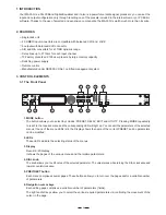
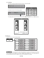
3.1 The Front Panel

3. CONTROL ELEMENTS

4

Single rack unit

2 COMBO input connectors are compatible with balanced XLR and JACK

2 outputs with balanced XLR connector

A/D and D/A converters for a 117dB dynamic range

Delay lines up to 2715ms for each input channel

10 Factory presets and 128 user presets by large memory capacity

Switching power supply

Remote control

Manufactured under QS9000, VDA6.1 certified management system

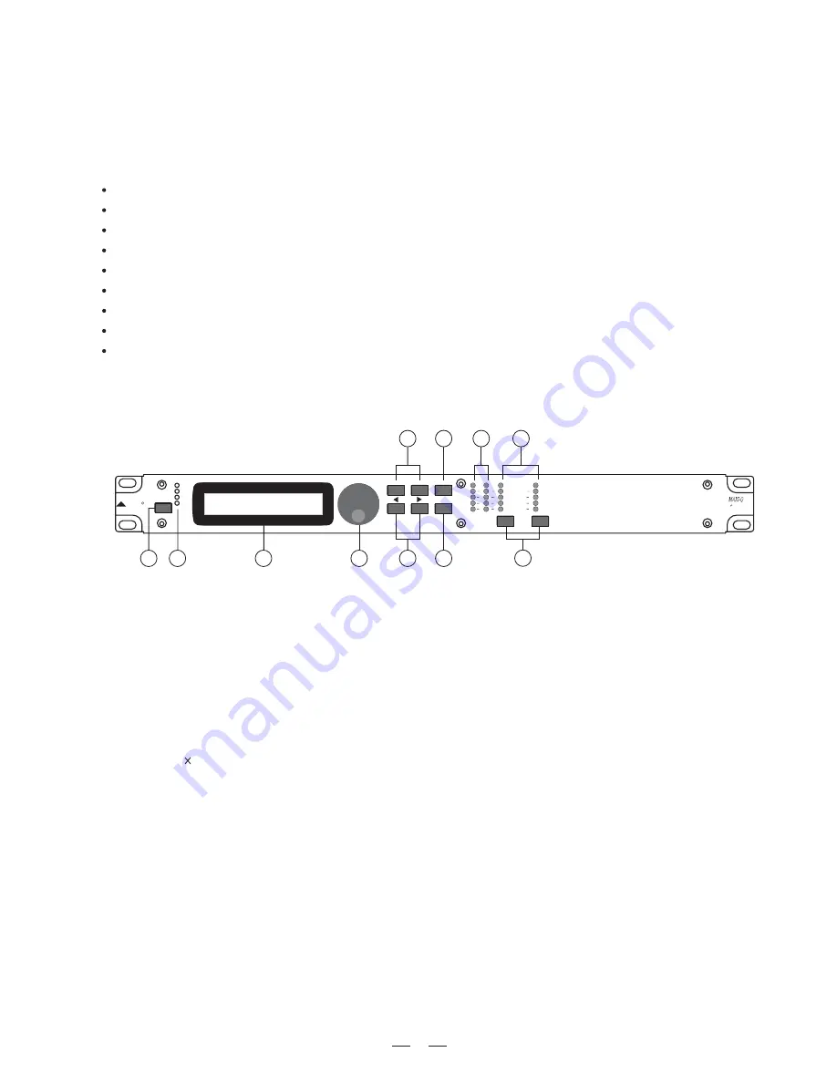
2.LEDs

These LEDs indicate the selecting status of the menus.

3.Display

Rear-lit 2 20 display.
It shows the pages of the various menus and the relative parameters.

4.DIAL knob

The knob allows you to edit value of the selected parameter. The value raises while turning the DIAL clockwise and
lowers counterclockwise.

6.Navigation cursor keys

Each editing page comprises a variable number of parameters (fields).
The right and left keys allow you to select the various required parameters via controlling the movement
cursor in the page.

of the

8

5

10

9

6

7

4

3

2

1

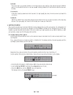
1.MODE button

The button allows you to select four modes: PRESET, DELAY, EDIT and UTILITY. Pressing MODE repeatedly
to reach to the required menu and the corresponding LED will light up. You can edit the parameters of the selected
menus. If none of the menu LEDs is lit, the Display shows the name of the current PRESET and no parameters
can be modified.

5.PREV/NEXT button

Each menu comprises several pages. These buttons allow you to turn over the pages and/or a variable number
of parameters.

Your MAXI-Q is a 30+30 Band Digital Equalizer and it also is a powerful versatile signal processor. you can set the
input and output configuration only through recalling one of the presets included in the internal memory or PC Editor
software. Thanks to the use of selected and expensive components, the MAXI-Q is worth much more than its price.

11

R

LTO

OUTPUT

LEVEL

1

OUTPUT

LEVEL

2

ENTER

PREV

NEXT

ESC

MODE

CLIP

6

12

18

24

A

B

INPUT LEVEL

MUTE

MUTE

30 30 BAND

DIGITAL EQUALIZER

PRESET

DELAY

EDIT

UTILITY

CLIP

6

12

18

24

CLIP

6

12

18

24

Summary of Contents for MAXI-Q

Page 1: ...MAXI Q 30 30 BAND DIGITAL EQUALIZER User s Manual LTO R www altoproaudio com Version 1 1 August 2005 English...

Page 2: ...ct away from naked flames Read these instructions Follow all instructions Keep these instructions Do not discard Heed all warnings Only use attachments accessories specified by the manufacturer Do not...

Page 3: ...are with you our work and our dreams paying attention to your suggestions and your comments Following this idea we create our products and we will create the new ones From our side we guarantee you an...

Page 4: ...put Signal 3 5 9 THE MENU MAP CONFIGURATION DESCRIPTION 5 1 Preset Menu 5 2 Delay Menu 5 3 Edit Menu 5 4 Utility Menu 6 CONNECTIONS 19 7 APPLICATION 20 8 OPERATION BLOCK DIAGRAM 21 9 TECHNICAL SPECIFI...

Page 5: ...ired parameters via controlling the movement cursor in the page of the 8 5 10 9 6 7 4 3 2 1 1 MODE button The button allows you to select four modes PRESET DELAY EDIT and UTILITY Pressing MODE repeate...

Page 6: ...und system are off to avoid the annoying and sometimes dangerous signal peaks Use it to connect your MAXI Q to the supplied AC cord Please check the Voltage in your country and what voltage for your M...

Page 7: ...of your sound system Then connect the main cord and only switch on the MAXI Q The display will show the data regarding with the operating system release for a few seconds The powerful versatile signal...

Page 8: ...ary Press the key until the menu LED lights up MODE EDIT Use the and keys to go to the page PREV NEXT Input Gain I n p u t G a i n example A 1 B 2 2 D E B A S S F 1 To execute the function of MEMORY I...

Page 9: ...nable you to work faster and safely Note In this first phase of setting up your sound system the adjustment of these functions which if not Indis pensable during installation can wait But do remember...

Page 10: ...ons 5 1 1 Load PRESET This menu page allows the required Preset to be loaded and made operatively L o a d 2 P r e s e t F D E B A S S A 1 B 2 2 F D E B A S S A 1 B 2 2 F D E B A S S 4 7 Number of PRES...

Page 11: ...s possible to load a modified Nevertheless Factory PRESET save it in a area modify it as required and then store it again in the same area User PRESET User Note PRESETS Scrolling through the memory ar...

Page 12: ...d system for example in large concert halls INA DELAY INB DELAY Parameters menu DELAY Parameters stadiums etc Thus achieving virtual alignment Press The page appears by means of which it s possible to...

Page 13: ...of the PRESET and according to settings Units UTLITY menu In fact these pages only show the parameters that can actually be used in the most suitable form of editing Parameters The measurement unit ca...

Page 14: ...alues are in the range 6dB 30dB with 0 5dB steps I n p u t G a i n I N A G A I N 2 5 d B Note Setting the input signal of a digital unit is particularly important much more than on an analog unit as a...

Page 15: ...50Hz 63Hz 25Hz 100Hz 125Hz 160Hz 200Hz 80Hz 315Hz 400Hz 500Hz 630Hz 250Hz 1KHz 1 25KHz 1 6KHz 2KHz 800Hz 3 15KHz 4KHz 5KHz 6 3KHz 2 5KHz 10KHz 12 5KHz 16KHz 20KHz 8KHz To adjust the setting of GEQ Us...

Page 16: ...es NAME PEQ 1 PEQ 1 PEQ 2 PEQ 2 PEQ 3 PEQ 3 PEQ 4 PEQ 4 PEQ 5 PEQ 5 BANDWIDTH GAIN FREQ 5 3 6 Parameter EQ PEQ Input equalizer with 5 parametric filters Allows to alter the overall tone of the signal...

Page 17: ...ed this submenu to choose the measurement units to be used with certain functions a Delay Unit Used to set the measurement units in which Delays are expressed DELAY menu The options include meters mil...

Page 18: ...Side Preset Change RX MAXI Q 2 MAXI Q 1 IGNORE 2 SideField 3 Concert1 4 Concert2 5 Concert3 6 Concert4 7 Remote1 8 Remote2 9 Remote2 Preset Change RX MAXI Q 3 SERIAL PORT SERIAL PORT SEND Preset 2 Pre...

Page 19: ...allows to set the delays during the sound check and only have to reset them automatically when necessary For example during a concert in the event of big jumps in temperature etc The editing values ar...

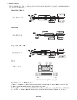
Page 20: ...PIN 3 PIN 2 RXD PIN3 GND PIN5 TXD PIN2 PIN 3 RXD PIN 2 TXD PIN 5 GND The wire must be changed between 2 3 pin 9 PIN 9 PIN Special attentions for R 232 interface S 1 Be careful not to use the pin to pi...

Page 21: ...14W 95 240V 50 60Hz FUSE 95 120V T500mAL 210 240V T315mAL RS485 OUT RS485 IN RS232 INPUT A INPUT B 2 1 OUTPUTS PUSH 2 1 3 NEW TIDE PUSH 1 3 2 NEW TIDE PUSH 1 3 2 NEW TIDE Apparaten skall anslutas till...

Page 22: ...15dB 15dB Step 0 5dB 30dB 6dB Step 0 5dB PEQ01 PEQ05 Frequency Bandwidth Gain Frequency Bandwidth Gain 15 6Hz 16KHz 0 05 3 00OCT 0 05OCT Step 15dB 15dB Step 0 5dB 0 05 3 00OCT 0 05OCT Step 15dB 15dB...

Page 23: ...48 kHz Features Delay Step 21 microseconds minimum Max Delay time 2715 ms EQ Gain 15dB variable in 0 5dB steps EQ Bandwidth 0 05 to 3 00 octaves variable in 0 05 steps PEQ freq 15 6 Hz to 16 kHz 24dB...

Page 24: ...LTO of 1 year from the purchase date if you have completed the Warranty Registration Card in time 3 3 During the warranty service may repair or replace this product at its own option at no charge to...

Page 25: ...13737 email alto altoproaudio com Fax 886 4 22346757 c All rights reserved to ALTO All features and content might be changed without prior notice Any photocopy translation or reproduction of part of t...

Reviews: