6
4. GETTING STARTED
4.1 Configuration of the system
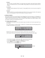
Meanwhile, the system will restore the exact operating conditions at the time of switching off.
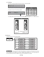
16.RS 232
This is the serial communication interface port. It allows incoming and outgoing communication between a MAXI-Q
and a PC or other MAXI-Q units. You can use the
LTO editing software to control functions of all the processor
remotely.
17.OUTPUTS
These two outputs are balanced XLR connectors. The high quality, low noise, 24 bit converters can make D/A
conversion.
18.INPUTS
INPUT A and INPUT B are compatible with balanced XLR and JACK. They are audio connectors of the respective
sections. The high quality, low noise, 24 bit converters can make A/D conversion.
At first, switch off the equipment, carry out the audio and power connection from the various components of your
sound system.
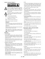
Then, connect the main cord and only switch on the MAXI-Q. The display will show the data regarding with the
operating system release for a few seconds.
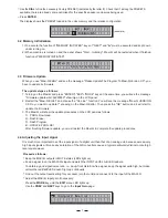
The powerful versatile signal processor MAXI-Q is mainly designed for use with audio systems. Its configurations of
the input and output can be only set by recalling one of the PRESETS included in the internal memory. So the user
must be very clear about the main function of the unit in order to get a best operation of your MAXI-Q. Before you start
your operation, please read the following parts carefully:
And the system Will enter into default status, showing the main operating information on the display.
A 1
B 2
1
F
F L A T
Load the
containing the
you've found.
Factory PRESET
configuration
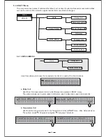
Press the
Key until the
menu LED lights up.
MODE
PRESET
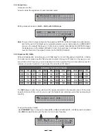
The display will show the
page:
Load PRESET
Set all the MAXI-Q outputs in MUTE status (LEDs lit) by pressing the relative keys.
(example)
L o a d
P r e s e t
1
F
F L A T
M A X
- Q
R e l e a s e
1 . 0
-
-
I


