Installation
Instruction manual 91/104 V9.2
4.3.3 Clamp resistor
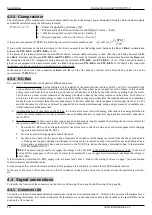
The rated power of this resistance (or resistor battery) shall be equal to the average power dissipated during the motor shutdown phase
and shall be calculated using the following formula:
P
=
0,2
⋅
J
⋅
2
⋅
F
P = Power dissipated by resistance [W]
J = Total moment of inertia on the motor shaft [Kg
·m²
]
(rotor + load)
ω = Maximum angular speed of the motor [rad/sec]
F = Repeat frequency of the work cycle [cycles/sec]
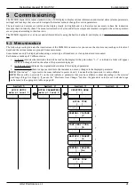
If the speed is expressed in “RPM” the following conversion formula must be used:
ω
[
rad
/
sec
]=
n
[
RPM
]
9,55
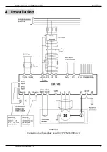
If you use the resistance of the internal clamp to the drive, you must leave the bridge wired between the
R-
and
Rint+
terminals and
between the
PTC-RES-
and
PTC-RES+
of X3.
If the power of the internal resistance is not sufficient and an external clamp resistance is used, then the wire bridge between the
R-
and
Rint+
terminals and between
PTC-RES- and
PTC-RES
+ of X3 must be removed: connect the resistance between the
Rest+
and
R-
terminals and the PTC temperature probe between the terminals
PTC-RES-
and
PTC-RES+
of X3. If the external resistance
group is not equipped with a temperature probe, the flush bridge between
PTC-RES-
and
PTC-RES+
of X3 shall be left connected:
in this case, overload protection on external resistors cannot work.
In the case of a drive size 1, the connection of
Rest+
and
R-
is on the X2 connector; instead, with a drive size 2 you have to use the
special screw TERMINALS.
4.3.4 DC-Bus
DC+ and DC- TERMINALS can be used for different purposes:
1. Balancing clamp energy
: having multiple drives installed in the same electrical cabinet, all DC+ and DC- terminals of the
various drives are connected in parallel, while maintaining the three-phase power supply for each of them. In this case the
energy recovered from the drive working as a brake is used partially or totally by the other drives operating from the motor.
This leads to a partial or total reduction of the energy discarded in heat by the clamp resistance of the drives. With this con-
nection the total recoverable energy is equal to the sum of the energy recoverable from the individual drives and sometimes
makes the use of external clamp resistors unnecessary. With this connection, the three-phase power supply (locks L1,L2,L3)
must be the same for all drives and must be supplied and removed simultaneously using a single contactor or multiple con-
trolled contactors at the same time.
2. Additional battery of capacitors on the dc-bus
: in order to store more recovered energy, then reduce the energy discarded in
heat in the clamp resistance, it is also possible to use an additional battery of capacitors appropriately sized and connected to
the DC BUS.
3. D.C.
Power supply
: In this case it is necessary to use an external power supply capable of providing the necessary current for
the operation of all the drives connected to it. This power supply must:
1. Power the DC BUS with a voltage that slowly rises from zero to the final value (to avoid current peaks while charging
capacitors mounted on the DC BUS).
2. Provide an end-of-charge signal to enable the drive.
3. Be able to send back into the power line or dissipate on resistance all the energy recovered from the drives connected to
it. If the power supply is designed to dissipate on resistance the recovered energy it is possible to use an additional capa-
citors battery appropriately sized and connected to the DC BUS to reduce the energy discarded in heat in the resistance
(ALTER module 13/007).
NOTE:
The power supply shall only supply the voltage on the DC-BUS if the DOK output is active at +24V; in the event
that the DOK output goes to 0V (in case of alarm for example) the power supply must immediately discharge the voltage to
the DC-BUS.
It is advisable to protect the DC-BUS supply with two fuses (see Table 2: Data for the sizing of drives on page 7) and use braided
cables (twistates) and shielded cables.
For the sizing of the various elements described in this paragraph it is advisable to contact the ALTER technical service.
In the case of drive size 1 this connection is on the X2 connector; instead, with a drive size 2 you have to use the special screw termin-
als.
4.4 Signal connections
To identify the location of the connectors on the drive, see Drawing 29 on page 85 and Drawing 30 on page 86.
4.4.1 Connector X3
Connection of the motor-mounted thermistor (maximum resistance at room temperature = 1KΩ) and the protection thermistor for ex-
ternal braking resistances. In case the terminals of the thermistor are on the connection cable to the transducer, the special PINs can be
used on the X4 connector.
14
Alter Elettronica s.r.l.


