Commissioning
Instruction manual 91/104 V9.2
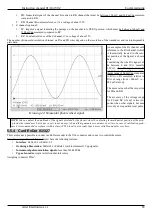
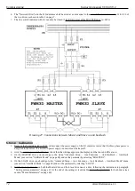
With reference to drawing 23 you can see a point called “F1 " that corresponds to the frequency (or RPM) of field weakening start
(i.e. when the torque begins to drop). This point is automatically calculated by the drive and is not accessible by the customer: it
depends on the ratio between the parameter “Maximum Voltage " and “Nominal Voltage".
At this point you can access the “Quick Setup → Motor Parameters → Motor Type " menu and start entering the above parameters
one by one: t he data must be inserted in the order as they are in the structure of the menu
because they are linked to each other and
some entered first must limit those inserted later.
The parameters of the menu group "Optional Param“ (see page 38) are not indispensable as they can be calculated automatically by
the Autotune procedure explained a little later.
5.4.2 Autotune for the calculation of optional parameters
In the event that the optional motor data (i.e. those contained in the menu group "Optional Param“ on page 38) are not available on the
motor plate, they must be automatically detected by the PWM3D drive.
To do this it is necessary to have first executed all the following points:
•
Entered ALL motor data indicated in the previous paragraph.
•
Have mechanically disconnected the motor shaft from the machine, as the motor will rotate without the control of the
external speed reference.
•
Have saved the motor parameters on Flash memory.
Since the supply of auxiliary services should already be present, follow these steps to complete the Autotune procedure:
1. Enable the function from the “Quick Setup → Motor Parameters → Autotune Mode” menu on “ENABLED”.
2. When the DOK output switches to ON and the green LED DOK turns on, you can give the three-phase/monophase power
supply on the terminals L1, L2, L2 or D.C. power supply on the DC-BUS if this mode has been selected (see Drawing 2 on
page 12 and menu ”Power supply from“ on page 57). After the charge of the capacitors on the DC-BUS, the RDY output
switches to the ON state and the green LED RDY turns on. From this point the drive is ready to be enabled for operation.
3. When the RDY output switches to ON status, you can enable the drive with the DEN command.
4. When the drive is enabled and works regularly in Autotune mode, the green RUN LED flashes and the DOK and RDY
outputs remain in ON status.
5. If the motor accelerates and rotates at the rated speed and the “Autotune " procedure does not end within 30 seconds, it
means that the continuous service current value set in the motor parameters is too low.
6. When the procedure of “Autotune” is finished the green LED RUN turns off. At that point you can remove the power rating
to the drive (DEN command = OFF) and remove the three-phase/monophase power supply (L1, L2, L3) or the D.C. power
supply on the DC-BUS. The RDY output is brought into the state of OFF and the green LED RDY turns off.
If at the end of the procedure there are no alarms on the display and the red FLT LED is off, then you can store the calculated data on
the Flash memory with the appropriate menu and mechanically reconnect the motor to the machine.
NOTE:
during operation of the motor in “Autotune " mode it is normal if it rotates clockwise and counter clockwise a few times
and then accelerates to the rated speed and then stops.
58
Alter Elettronica s.r.l.
Drawing 23: Power and torque curve / RPM


