background image

IS230-10GP Industrial layer 2 Switch Web User Guide

127

System Log

Logging Service

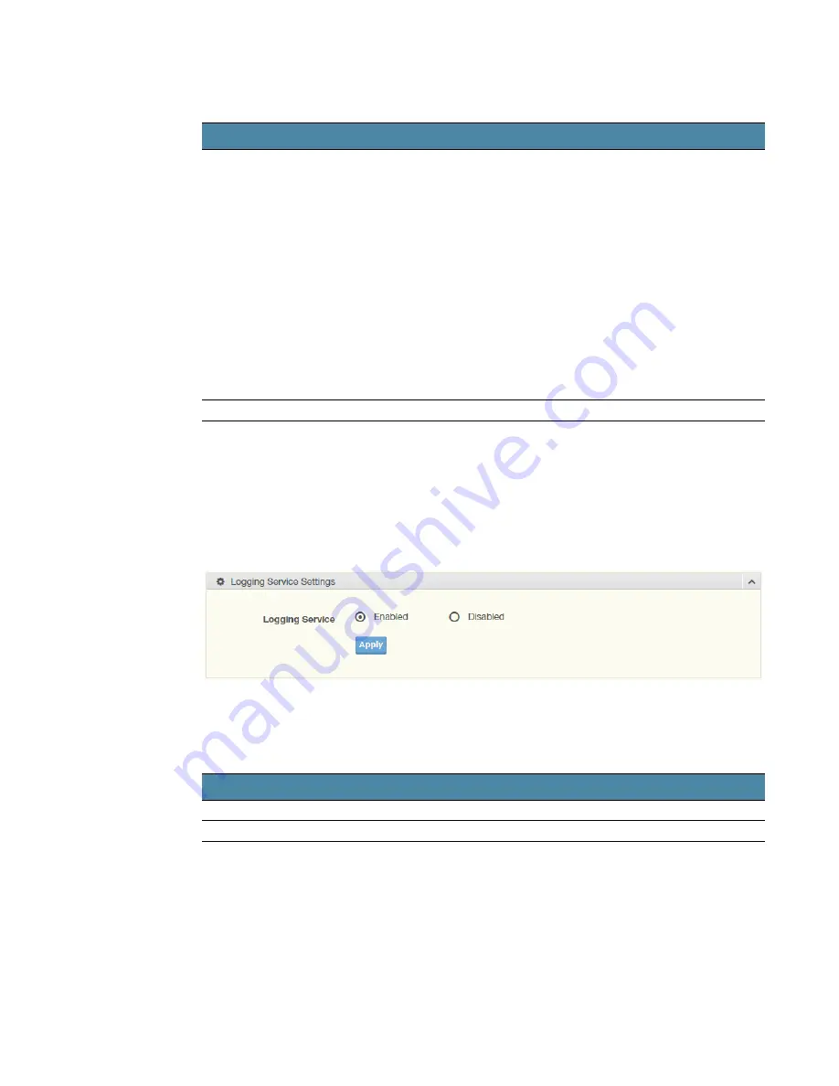
The Logging Service page allows you to setup the logging services feature 
for the system log.
To access this page, click 

Diagnostics

 > 

System Log

 > 

Logging 

Service

.

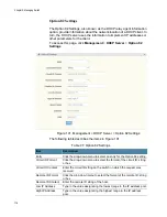
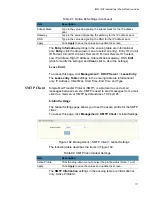
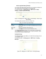
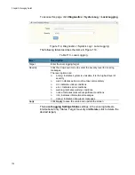
Figure 113. Diagnostics > System Log > Logging Service

The following table describes the items in Figure 113.

The 

Logging Information

 settings in the ensuing table are informational 

only: Logging Service.

Local Logging

The Local Logging page allows you to designate a local target when the 
severity criteria is reached.

Ping Results

Display the reply format of ping.
PING 2222::777 (2222::777): 56 data bytes

--- 2222::777 ping statistics ---
4 packets transmitted, 0 packets received, 100% packet loss
Or
PING 2222::717 (2222::717): 56 data bytes
64 bytes from 2222::717: icmp6_seq=0 ttl=128 time=10.0 ms
64 bytes from 2222::717: icmp6_seq=1 ttl=128 time=0.0 ms
64 bytes from 2222::717: icmp6_seq=2 ttl=128 time=0.0 ms
64 bytes from 2222::717: icmp6_seq=3 ttl=128 time=0.0 ms

--- 2222::717 ping statistics ---
4 packets transmitted, 4 packets received, 0% packet loss
round-trip min/avg/max = 0.0/2.5/10.0 ms

Apply

Click 

Apply

 to display ping result for the IP address.

Table 108. IPv6 Ping Test (Continued)

Item

Description

Table 109. Logging Service

Item

Description

Logging Service

Click Enabled or Disabled to set the Logging Service status.

Apply

Click 

Apply

 to save the values and update the screen.

Summary of Contents for IS230-10GP

Page 1: ...613 002603 Rev B IS230 10GP Industrial Ethernet Layer 2 Switch Web User Guide ...

Page 2: ...Allied Telesis and the Allied Telesis logo are trademarks of Allied Telesis Inc All other product names company names logos or other designations mentioned herein are trademarks or registered trademarks of their respective owners Allied Telesis Inc reserves the right to make changes in specifications and other information contained in this document without prior written notice The information prov...

Page 3: ...nd Line Interface CLI 26 Accessing the CLI 26 Web Browser Configuration 27 Default Network Configuration 27 Log In 27 Change Default Password 28 Chapter 2 Managing Switch 31 Monitoring 32 Device Information 32 Logging Message 33 Port Monitoring 34 Port Statistics 34 Port Utilization 35 Link Aggregation 36 LLDP Statistics 36 IGMP Statistics 37 MLD Statistics 38 System 39 IP Settings 39 IPv6 Setting...

Page 4: ...Settings 62 MLD Querier 63 MLD Static Groups 64 Multicast Groups 64 Router Ports 64 Jumbo Frame 65 Spanning Tree 65 STP Global Settings 65 STP Port Settings 66 STP Bridge Settings 67 STP Port Advanced Settings 68 MST Config Identification 69 MST Instance ID Settings 69 MST Instance Priority Settings 70 MST Instance Info 70 STP Statistics 71 X Ring Elite 71 X Ring Elite Settings 71 X Ring Elite Gro...

Page 5: ... Settings 93 QoS Scheduling 93 CoS Mapping 95 DSCP Mapping 96 IP Precedence Mapping 97 QoS Basic Mode 98 Global Settings 98 Port Settings 98 Rate Limit 99 Ingress Bandwidth Control 99 Egress Bandwidth Control 100 Egress Queue 100 Management 102 LLDP 102 LLDP System Settings 102 LLDP Port Settings 103 LLDP Local Device Info 105 LLDP Remote Device Info 106 LLDP Overloading 106 SNMP 106 SNMP Settings...

Page 6: ...gs Window 119 Sending Message 119 RMON 120 RMON Statistics 120 RMON History 121 RMON Alarm 122 RMON Event 123 Diagnostics 124 Cable Diagnostics 124 Ping Test 124 IPv6 Ping Test 126 System Log 127 Logging Service 127 Local Logging 127 System Log Server 129 DDM 130 LED Indication 131 Tools 132 Backup Manager 132 Upgrade Manager 134 Dual Image 135 Save Configuration 135 User Account 135 Reset System ...

Page 7: ...Contents 8 ...

Page 8: ...PVID Settings 53 Figure 27 L2 Switching 802 1Q VLAN Port to VLAN 54 Figure 28 L2 Switching Q in Q Global Settings 55 Figure 29 L2 Switching Q in Q Port Settings 56 Figure 30 L2 Switching GARP GARP Settings 57 Figure 31 L2 Switching GARP GVRP Settings 58 Figure 32 L2 Switching 802 3az EEE 58 Figure 33 L2 Switching Multicast Multicast Filtering 59 Figure 34 L2 Switching Multicast IGMP Snooping IGMP ...

Page 9: ...ure 80 QoS QoS Basic Mode Global Settings 98 Figure 81 QoS QoS Basic Mode Port Settings 98 Figure 82 QoS Rate Limit Ingress Bandwidth Control 99 Figure 83 QoS Rate Limit Egress Bandwidth Control 100 Figure 84 QoS Rate Limit Egress Queue 100 Figure 85 Management LLDP LLDP System Settings 102 Figure 86 Management LLDP LLDP Port Settings LLDP Port Configuration 103 Figure 87 Management LLDP LLDP Port...

Page 10: ...ervice 127 Figure 114 Diagnostics System Log Local Logging 128 Figure 115 Diagnostics System Log System Log Server 129 Figure 116 Diagnostics DDM Alarm 130 Figure 117 Diagnostics DDM Alarm Info 130 Figure 118 Diagnostics LED Indication 131 Figure 119 Tools Backup Manager 132 Figure 120 Tools Upgrade Manager 134 Figure 121 Tools Dual Image 135 Figure 122 Tools User Account 135 ...

Page 11: ...Figures 12 ...

Page 12: ... Management 52 Table 23 PVID Settings 53 Table 24 Port to VLAN 54 Table 25 Q in Q Global Settings 55 Table 26 Q in Q Port Settings 56 Table 27 GARP Settings 57 Table 28 GVRP Settings 58 Table 29 802 3az EEE 58 Table 30 Multicast Filtering 59 Table 31 IGMP Settings 60 Table 32 IGMP Querier 61 Table 33 IGMP Static Groups 61 Table 34 MLD Settings 63 Table 35 MLD Querier 63 Table 36 MLD Static Group 6...

Page 13: ...Table 78 QoS Basic Mode Port Settings 99 Table 79 Ingress Bandwidth Control 99 Table 80 Egress Bandwidth Control 100 Table 81 Egress Queue 101 Table 82 LLDP System Settings 102 Table 83 LLDP Port Configuration 103 Table 84 Optional TLVs Selection 104 Table 85 VLAN Name TLV VLAN Selection 105 Table 86 LLDP Remote Device Info 106 Table 87 SNMP Settings 107 Table 88 SNMP Community 107 Table 89 SNMP U...

Page 14: ...n Guide 15 Table 110 Local Logging 128 Table 111 System Log Server 129 Table 112 DDM Alarm 130 Table 113 DDM Alarm Info 130 Table 114 DDM Alarm 131 Table 115 Backup Manager 132 Table 116 Upgrade Manager 134 Table 117 Dual Image 135 Table 118 User Account 136 ...

Page 15: ...Tables 16 ...

Page 16: ... contains the hardware installation instructions for the IS230 10GP Industrial Managed Switch The preface contains the following sections Safety Symbols Used in this Document on page 18 Contacting Allied Telesis on page 19 ...

Page 17: ...m you that performing or omitting a specific action may result in equipment damage or loss of data Warning Warnings inform you that performing or omitting a specific action may result in bodily injury Warning Laser warnings inform you that an eye or skin hazard exists due to the presence of a Class 1 laser device Warning Warnings inform you of hot surfaces ...

Page 18: ...s to learn about RMAs and to contact Allied Telesis technical experts USA and EMEA phone support Select the phone number that best fits your location and customer type Hardware warranty information Learn about Allied Telesis warranties and register your product online Replacement Services Submit a Return Merchandise Authorization RMA request via our interactive support center Documentation View th...

Page 19: ...Preface 20 ...

Page 20: ...21 Chapter 1 Configuration Utility This chapter contains the following sections First Time Setup on page 22 Command Line Interface Configuration on page 26 Web Browser Configuration on page 27 ...

Page 21: ...ne active route between each pair of network nodes and provides automatic fail over to the next available redundant route A brief explanation of how RSTP works is given in the Spanning Tree section The switch is capable of communicating with other SNMP capable devices on the network to exchange management information This statistical derived information from the network is saved in the Management ...

Page 22: ...rd When logging into any of the administrative interfaces for the first time use the default username and password They are Username manager Password friend Note Both the user name and password are case sensitive Allied Telesis recommends that you change to a new password when you initially configure the switch If you are using the graphical web interface go to Change Default Password on page 28 I...

Page 23: ...h for network access select Add Menu Address Here to reach the System Settings menu The settings in this menu control the switch s general network configuration DHCP Enabled Disabled The switch can automatically obtain an IP address from a server using the Dynamic Host Configuration Protocol DHCP This can speed up initial set up as the network administrator does not have to find an open IP address...

Page 24: ...negotiation such that the fastest bandwidth is selected Choose to enable auto negotiation or use fixed settings 100Mbps Fiber ports are Fixed speed only Speed Duplex Flow Control The managed switch accepts three local area network Ethernet Standards The first standard 10BASE T runs 10Mbps with twisted pair Ethernet cable between network interfaces The second local area network standard is 100BASE ...

Page 25: ... mask and default gateway value is the new value of the parameter If value is omitted the current value is displayed Please note that new values will not take effect until explicitly committed Sections and parameter names are case sensitive e g Network is not the same as network Note Any commands in the CLI Commands section of this chapter with the exception of the global commands must be prefaced...

Page 26: ... Gateway 192 168 1 254 DNS Server 1 168 95 1 1 DNS Server 2 168 95 192 1 The default User Name is manager and the default password is friend Both the user name and password are case sensitive Log In To start a network management session perform the following procedure 1 Connect one of the Ethernet ports on the switch to an existing network 2 Connect your computer console to the same local area net...

Page 27: ... Monitor Device Information Change Default Password In keeping with good management and security practices it is recommended that you change the default password as soon as the device is functioning and setup correctly The following procedure details the necessary steps to change an existing password 1 Navigate to Tools User Account The Add Edit User window displays For more information about the ...

Page 28: ...m the Password Type drop down menu select Clear Text Encrypted or No Password 4 In the Password field type in the new password The password is case sensitive 5 Enter the identical password in the Retype Password field 6 Click Apply to add the current account settings If a new User Name has been defined a new line is displayed along with other user names in the Local Users table shown just below th...

Page 29: ...Chapter 1 Configuration Utility 30 ...

Page 30: ... of the IS230 10GP management windows and contains the following sections Monitoring on page 32 System on page 39 L2 Switching on page 46 MAC Address Table on page 77 Security on page 80 QoS on page 92 Management on page 102 Diagnostics on page 124 Tools on page 132 ...

Page 31: ...tistics on page 37 MLD Statistics on page 38 Device Information The Device Information menu lists information such as System Name System Location MAC Address Firmware version and more pertaining to the system The information is for review only To modify the device information see the respective item within the user interface To access this page click Monitoring Device Information Figure 4 Monitori...

Page 32: ...ric characters default is Default MAC Address Displays the MAC address of the switch IP Address Displays the assigned IP address of the switch Subnet Mask Displays the assigned subnet mask of the switch Gateway Displays the assigned gateway of the switch Loader Version Displays the current loader version of the switch Loader Date Displays the current loader build date of the switch Firmware Versio...

Page 33: ...o designate a severity level for the Logging Message Filter function Click the drop down menu to select the severity level target setting The level options are n emerg Indicates system is unusable It is the highest level of severity n alert Indicates action must be taken immediately n crit Indicates critical conditions n error Indicates error conditions n warning Indicates warning conditions n not...

Page 34: ...olErrors dot3ControlInUnknownOpcodes dot3InPauseFrames and dot3OutPauseFrames The Rmon MIB Counters settings in the ensuing table are informational only etherStatsDropEvents etherStatsOctets etherStatsPkts etherStatsBroadcastPkts etherStatsMulticastPkts etherStatsCRCAlignErrors etherStatsUnderSizePkts etherStatsOverSizePkts etherStatsFragments etherStatsJabbers etherStatsCollisions etherStatsPkts6...

Page 35: ...The following table describes the items in Figure 8 The fields in the LLDP Global Statistics table are for information only Insertions Deletions Drops and Age Outs The fields in the LLDP Port Statistics table are for information only Port TX Frames Total RX Frames Total Discarded and Errors RX TLVs Discarded and Unrecognized and RX Ageouts Total Table 4 Port Utilization Item Description Refresh pe...

Page 36: ...s settings in the ensuing table are informational only Total RX Valid RX Invalid RX Other RX Leave RX Report RX General Query RX Special Group Query RX Special Group Source Query RX Leave TX Report TX General Query TX Special Group Query TX and Special Group Source Query TX Table 6 IGMP Statistics Item Description Clear Click Clear to refresh IGMP Statistics of all the interfaces Refresh Click Ref...

Page 37: ...stics settings in the ensuing table are informational only Total RX Valid RX Invalid RX Other RX Leave RX Report RX General Query RX Special Group Query RX Special Group Source Query RX Leave TX Report TX General Query TX Special Group Query TX and Special Group Source Query TX Table 7 MLD Statistics Item Description Clear Click Clear to refresh MLD Statistics of all the interfaces Refresh Click R...

Page 38: ...he configurable settings for the static option To access this page click System IP Settings Figure 11 System IP Settings The following table describes the items in Figure 11 Table 8 IP Settings Item Description Mode Click the radio button to select the IP Address Setting mode Static DHCP or BOOTP IP Address Enter a value to specify the IP address of the interface The default is 192 168 1 1 Subnet ...

Page 39: ...se Router IPv6 Static Address IPv6 Static Router and DHCPv6 Client DNS Server 1 Enter a value to specify the DNS server 1 for the interface The default is 168 95 1 1 DNS Server 2 Enter a value to specify the DNS server 2 for the interface The default is 168 95 192 1 Apply Click Apply to save the values and update the screen Table 8 IP Settings Continued Item Description Table 9 IPv6 Settings Item ...

Page 40: ...2 Item Description Mode Click the radio button to enable or disable the DHCP Client Option 82 mode Circuit ID Format Click the drop down menu to set the ID format String Hex User Defi nition Circuit ID String Enter the string ID of the corresponding class Circuit ID Hex Enter the hex string of the corresponding class Circuit ID User Define Enter the user definition of the corresponding class Remot...

Page 41: ...m DHCP Auto Provision The following table describes the items in Figure 14 The DHCP Auto Provision Information settings in the ensuing table are informational only Status Management VLAN By default the VLAN is the management VLAN providing communication with the switch management interface To access this page click System Management VLAN Figure 15 System Management VLAN The following table describ...

Page 42: ... in Figure 16 Table 13 System Time Item Description Enable SNTP Click the radio button to enable or disable the SNTP SNTP FNT Address Enter the address of the SNTP server This is a text string of up to 64 characters containing the encoded unicast IP address or hostname of a SNTP server Unicast SNTP requests will be sent to this address If this address is a DNS hostname then that hostname should be...

Page 43: ...e and time of the system Time Zone Click the drop down menu to select a system time zone Daylight Saving Time Click the drop down menu to enable or disable the daylight saving time settings Daylight Saving Time Offset Enter the offsetting variable in seconds to adjust for daylight saving time Recurring From Click the drop down menu to designate the start date and time for daylight saving time Recu...

Page 44: ...7 on page 44 The Network Port Information settings in the ensuing table are informational only Protocol Name and Port Value Table 14 Network Port Settings Item Description HTTP Enter the HTTP Port address HTTPS Enter the HTTPS Port address TELNET Enter the TELNET Port address SSH Enter the SSH Port address ...

Page 45: ... Pro on page 72 Loopback Detection on page 75 Port Configuration Port Configuration describes how to use the user interface to configure LAN ports on the switch To access this page click L2 Switching Port Configuration Figure 18 L2 Switching Port Configuration The following table describes the items in Figure 18 Table 15 L2 Switching Port Configuration Item Description Port Click the drop down men...

Page 46: ...ting values To access this page click L2 Switching Port Mirror Figure 19 L2 Switching Port Mirror The following table describes the items in Figure 19 Speed Click the drop down menu to select the port speed Auto Auto 10M Auto 100M Auto 1000M Auto 10 100M 10M 100M or 1000M Duplex Click the drop down menu to select the duplex setting Half or Full Flow Control Click the radio button to enable or disa...

Page 47: ...tems in Figure 20 The Load Balance Information settings in the ensuing table are informational only Load Balance Algorithm LAG Management Link aggregation is also known as trunking It is a feature available on the Ethernet gateway and is used with Layer 2 Bridging Link aggregation Destination Port Click the drop down menu to select the destination port and receive all the traffic from configured m...

Page 48: ...ings and Clear click to load default settings LAG Port Settings The LAG Port Settings page allows you to enable or disable set LAG status speed and flow control functions In this example we will configure a LAG between the following switches To access this page click L2 Switching Link Aggregation LAG Port Settings Table 18 LAG Management Item Description LAG Click the drop down menu to select the ...

Page 49: ...ble describes the items in Figure 23 The LACP Information settings in the ensuing table are informational only System Priority Table 19 LAG Port Settings Item Description LAG Select Click the drop down menu to select a predefined LAG trunk definition LAG 1 8 Enabled Click the radio button to enable or disable the LAG Port Speed Click the drop down menu to select the port speed Auto Auto 10M Auto 1...

Page 50: ...th the 802 1Q feature you can preserve VLAN IDs and segregate different VLAN traffic The 802 1Q VLAN tag feature encapsulates the 802 1Q VLAN tagging within another 802 1Q VLAN tag The outer tag is assigned following the AP group while the inner VLAN ID is assigned dynamically by the AAA server Table 21 LACP Port Settings Item Description Port Select Select a port for the LACP Port Settings The li...

Page 51: ...gs in the ensuing table are informational only VLAN ID VLAN Name VLAN Type and Edit click to enter VLAN name PVID Settings The PVID Settings page allows you to designate a PVID for a selected port define the accepted type and enable disable the ingress filtering Table 22 VLAN Management Item Description VLAN Action Click the radio button to add or delete the VLAN entry shown in the previous field ...

Page 52: ...you want assigned to untagged or priority tagged frames received on this port The value ranges 1 to 4094 The default is 1 Accepted Type Click the radio button to specify which frames to forward Tag Only discards any untagged or priority tagged frames Untag Only discards any tagged frames All accepts all untagged and tagged frames Whichever you select VLAN tagged frames are forwarded in accor dance...

Page 53: ...ort Mode administrative VLANs and Operational VLANs Table 24 Port to VLAN Item Description Port Displays the assigned port to the entry Interface VLAN Mode Displays the assigned mode to the listed VLAN port n Hybrid Port hybrid model n Access Port hybrid model n Trunk Port hybrid model n Tunnel Port hybrid model Membership Displays the assigned membership status of the port entry options include F...

Page 54: ...ly is handled by the switch so the attached machine sees single tagged 802 1Q VLAN frames or via a double tagged trunk port where both inner and outer VLANs are handled by the attached machine which sees double tagged 802 1ad VLAN frames Global Settings The Global Settings page allows you to set the outer VLAN Ethertype setting To access this page click L2 Switching Q in Q Global Settings Figure 2...

Page 55: ...on of attributes network identifiers or addresses by end stations and switches with each other Table 26 Q in Q Port Settings Item Description Port Select Enter the switch port part of VLAN configuration to configure the selection as a tunnel port Outer PVID Enter the Port VLAN ID PVID to assigned the native VLAN ID All untagged traffic coming in or out of the 802 1Q port is forwarded based on the ...

Page 56: ...e of this timer exists for each GARP participant for each port Leave Time Enter a value to specify the time to wait after receiving an unregister request for a VLAN or multicast group before deleting the associated entry in centiseconds This allows time for another station to assert registration for the same attribute in order to maintain uninterrupted service Enter a number between 12 and 3000 An...

Page 57: ...icient Ethernet EEE compliance Inactive link detection Inactive link detection function automatically reduces power usage when inactive links or devices are detected To access this page click L2 Switching 802 3az EEE Figure 32 L2 Switching 802 3az EEE The following table describes the items in Figure 32 Table 28 GVRP Settings Item Description Status Click to enable or disable the GARP VLAN Registr...

Page 58: ...ribes the items in Figure 33 The Properties Information settings in the ensuing table are informational only Unknown Multicast Action IGMP Snooping IGMP Snooping is defined as the process of listening to Internet Group Management Protocol IGMP network traffic IGMP Snooping allows a network switch to listen in on the IGMP conversation between hosts and routers and maintain a map of which links need...

Page 59: ...s Auto Learn Query Robustness Query Interval sec Query Max Response Interval sec Last Member Query count Last Member Query Interval sec Immediate Leave and Edit click to modify the settings IGMP Querier IGMP Querier allows snooping to function by creating the tables for snooping General queries must be unconditionally forwarded by all switches involved in IGMP snooping Table 31 IGMP Settings Item ...

Page 60: ...ess this page click L2 Switching Multicast IGMP Snooping IGMP Static Groups Figure 36 L2 Switching Multicast IGMP Snooping IGMP Static Groups The following table describes the items in Figure 36 Table 32 IGMP Querier Item Description VLAN ID Select the VLAN ID to define the local IGMP querier Querier State Select Disable or Enable to configure the VLAN ID IGMP Querier Querier Version Select the qu...

Page 61: ...e are informational only VLAN ID Port and Expiry Time Sec MLD Snooping The MLD Snooping allows you to select the snooping status enable or disable the version v1 or v2 and the enabling disabling of the report suppression for the MLD querier which sends out periodic general MLD queries and are forwarded through all ports in the VLAN MLD Settings To access the MLD Snooping Settings page click L2 Swi...

Page 62: ...ed To access this page click L2 Switching Multicast MLD Snooping MLD Querier Figure 38 L2 Switching Multicast MLD Snooping MLD Querier The following table describes the items in Figure 38 Table 34 MLD Settings Item Description MLD Snooping State Select Enable or Disable to setup the MLD Snooping State MLD Snooping Version Select the querier version V1 or V2 designated to the MLD Snooping Version M...

Page 63: ...ess Member Ports and Modify Multicast Groups To access this page click L2 Switching Multicast MLD Snooping Multicast Groups This page is informational only The Multicast Groups settings in the ensuing table are informational only ID Group IP Address Member Ports Type and Life Sec Router Ports To access this page click L2 Switching Multicast MLD Snooping Router Ports This page is informational only...

Page 64: ...anning Tree The Spanning Tree Protocol STP is a network protocol to ensure loop free topology for any bridged Ethernet local area network STP Global Settings The STP Global Settings page allows you to set the STP status select the configuration for a BPDU packet choose the path overhead force version and set the configuration revision range To access this page click L2 Switching Spanning Tree STP ...

Page 65: ...ttings The following table describes the items in Figure 42 Table 38 STP Global Settings Item Description Enabled Click the radio button to enable or disable the STP status BPDU Forward Select flooding or filtering to designate the type of BPDU packet PathCost Method Select short or long to define the method of used for path cost calcula tions Force Version Click the drop down menu to select the o...

Page 66: ...ribution For a root port the root path cost for the bridge 0 means Auto Edge Port Click the drop down menu to set the edge port configuration n No Force to false state as link to a bridge n Yes Force to true state as link to a host P2P MAC Click the drop down menu to set the Point to Point port configuration n No Force to false state n Yes Force to true state Migrate Click the check box to enable ...

Page 67: ... ensuing table are informational only Port Identifier Priority Port Id Path Cost Conf Oper Designated Root Bridge Root Path Cost Designated Bridge Edge Port Conf Oper P2P MAC Conf Oper Port Role and Port State Forward Delay Enter the variable 4 to 30 to set the forward delay for STP bridge set tings Max Age Enter the variable 6 to 40 to set the Max age for STP bridge settings Tx Hold Count Enter t...

Page 68: ...he ensuing table are informational only Configuration Name and Revision Level MST Instance ID Settings The MST Instance ID Settings page allows you to edit the MSTI ID and VID List settings To access this page click L2 Switching Spanning Tree MST Instance ID Settings Figure 46 L2 Switching Spanning Tree MST Instance ID Settings Table 42 MST Config Identification Item Description Configuration Name...

Page 69: ...nformational only MSTI ID Priority and Action MST Instance Info To access this page click L2 Switching Spanning Tree MST Instance Info The tables in this window are informational only The STP Bridge Status settings in the ensuing table are informational only Bridge Identifier Designated Root Bridge Root Path Cost Designated Bridge Root Port and TCNLast Topology Change Table 43 MST Instance ID Sett...

Page 70: ...apid Spanning Tree and a rapid auto recovery in the event that the network suffers a corrupt or broken link and prevents network loops X Ring Elite Settings The X Ring Elite Settings allows you to enable or disable the state of the X Ring settings To access this page click L2 Switching X Ring Elite X Ring Elite Settings Figure 48 L2 Switching X Ring Elite X Ring Elite Settings The following table ...

Page 71: ...or broken link and prevents network loops X Ring Pro Settings The X Ring Pro Settings page allows you to configure the status enabled or disabled of the function To access this page click L2 Switching X Ring Pro X Ring Pro Settings Figure 50 L2 Switching X Ring Pro X Ring Pro Settings Table 46 X Ring Elite Groups Item Description Ring ID Enter a number to specifies a ranging from 1 to 255 to ident...

Page 72: ...4 Couple Settings on page 74 Pair Settings on page 75 X Ring Pro Groups Settings Figure 51 L2 Switching X Ring Pro X Ring Pro Groups X Ring Pro Groups Settings The following table describes the items in Figure 51 Table 47 X Ring Pro Settings Item Description State Select Enabled or Disabled to setup the X Ring Pro mode Apply Click Apply to save the values and update the screen Table 48 X Ring Pro ...

Page 73: ...ble 49 Chain Setting Item Description Chain Ring ID Enter a number to specifies a ranging from 1 to 255 to identify a given X Ring group Role Click the drop down menu to designate the Role Head Port Click the drop down menu to designate the head port Member Port Click the drop down menu to designate the member port Add Click Add to save the values and update the screen Table 50 Couple Setting Item...

Page 74: ...he Global Settings page allows you to configure the state enabled or disabled of the function select the interval at which frames are transmitted and the delay before recovery To access this page click L2 Switching Loopback Detection Global Settings Figure 55 L2 Switching Loopback Detection Global Settings Table 51 Pair Setting Item Description Pair Ring ID Enter a number to specifies a ranging fr...

Page 75: ...e Loopback Detection Port Information settings in the ensuing table are informational only Port Enable State and Loop Status Table 52 Loopback Detection Global Settings Item Description State Select Enabled or Disabled to setup the loopback mode Interval Enter the variable in seconds 1 to 32767 to set the interval at which frames are transmitted Recover Time Enter the variable in seconds 60 to 100...

Page 76: ...d Port To access this page click MAC Address Table Static MAC Figure 57 MAC Address Table Static MAC The following table describes the items in Figure 57 The Static MAC Status settings in the ensuing table are informational only No MAC Address VLAN Port and Delete click to delete the desired MAC address Table 54 Static MAC Item Description MAC Address Enter the MAC address to which packets are sta...

Page 77: ...rt each hardware address is associated with The VLAN to show or clear dynamic MAC entries The MAC address selection To access this page click MAC Address Table Dynamic Forwarding Table Figure 59 MAC Address Table Dynamic Forwarding Table The following table describes the items in Figure 59 Table 55 MAC Aging Time Item Description Aging Time Enter the variable 10 to 630 to define the time required ...

Page 78: ...dress list VLAN Click the drop down menu to select the VLAN to show or clear dynamic MAC entries MAC Address Enter the MAC address to show or clear dynamic MAC entries If a port VLAN or MAC address is not selected the whole dynamic MAC table is displayed or cleared View Click View to display the MAC address information Clear Click Clear to clear the MAC Address Information table Table 56 Dynamic F...

Page 79: ...ket flooding on the LAN and consequent traffic to prevent the degrading of network performance Global Settings To access this page click Security Storm Control Global Settings Figure 60 Security Storm Control Global Settings The following table describes the items in Figure 60 Table 57 Storm Control Global Settings Item Description Unit Select pps or bps control units for the Storm Control functio...

Page 80: ...l Port Settings Item Description Port Enter the port number to designate the local port for the Storm Control function Port State Select Disabled or Enabled to define the port state Action Click the drop down menu to select the type of action to designate for the selected port during a Storm Control incident The options are Drop and Shutdown Type Enable Click the radio button to enable Broadcast U...

Page 81: ...nformational only Port Enabled FDB Learn Limit and Violation MAC Notification Protected Ports The Protected Port page allows you to configure a single or multiple ports as a protected or unprotected type To access this page click Security Protected Ports Figure 63 Security Protected Ports Table 59 Port Security Item Description Port Select Enter a single or multiple port numbers to configure Enabl...

Page 82: ...ed the denial of service DoS Global Settings The DoS Global Settings page allows you to configure enabled or disabled the setting for each function To access this page click Security DoS Prevention DoS Global Settings Figure 64 Security DoS Prevention DoS Global Settings Table 60 Protected Ports Item Description Port List Enter the port number to designate for the Protected Port setting Port Type ...

Page 83: ... 0 to 65535 to set the minimum fragment size when the function is enabled ICMP Fragments Click Enabled or Disabled to define the ICMP Fragments function IPv4 Ping Max Size Click Enabled or Disabled to set the maximum ping size for the IPv4 protocol IPv6 Ping Max Size Click Enabled or Disabled to set a maximum ping size for the IPv6 protocol Ping Max Size Set ting Enter the variable in bytes 0 to 6...

Page 84: ... ensuing table are informational only Port and DoS Protection Applications The Applications function allows you to configure various types of AAA lists TELNET The TELNET page allows you to combine all kinds of AAA lists with the Telnet line To access this page click Security Applications TELNET Figure 66 Security Applications TELNET Table 62 DoS Port Settings Item Description Port Select the port ...

Page 85: ...ns SSH The following table describes the items in Figure 67 The SSH Information settings in the ensuing table are informational only SSH Table 63 TELNET Item Description Telnet Service Click Enabled or Disabled to set remote access through the Telnet Service function Apply Click Apply to save the values and update the screen Disconnect Click Disconnect to disable the current Telnet service Table 6...

Page 86: ... informational only HTTP Service and Session Timeout HTTPS The HTTPS page allows you to combine all kinds of AAA lists on the HTTPS line Attempts to access the switch s Web UI from HTTPS are first authenticated To access this page click Security Applications HTTPS Figure 69 Security Applications HTTPS Table 65 HTTP Item Description HTTP Service Click Enabled or Disabled to set up Ethernet encapsul...

Page 87: ...thentication period To access this page click Security 802 1x 802 1x Settings Figure 70 Security 802 1x 802 1x Settings The following table describes the items in Figure 70 Table 66 HTTPS Item Description HTTPS Service Click Enabled or Disabled to set up Ethernet encapsulation over HTTPS Session Timeout Enter the variable in minutes 0 to 86400 to define the timeout period for the HTTP session Appl...

Page 88: ... Port State Accounting Port Enter the port number 1 to 65535 assigned to the listed server IP configured to provide authorization and authentication for network access Security Key Enter the variable to define the network security key used in authenti cation Reauth Period Enter the variable in seconds to define the period of time between authentication attempts Apply Click Apply to save the values...

Page 89: ...able describes the items in Figure 72 The IP Security Status settings in the ensuing table are informational only IP Security Entry Settings Once the Global Setting is enabled use the Entry Settings to define an IP Security entry To access this page click Security IP Security Entry Settings Figure 73 Security IP Security Entry Settings Table 69 IP Security Global Settings Item Description Status C...

Page 90: ... informational only IP Address IP Mask Services and Action Table 70 IP Security Entry Settings Item Description IP Address Enter the source IP address to apply the IP Security function IP Mask Enter the IP address for use in masking the previous IP Address Services Enter the type of services to associate with the entry setting Apply Click Apply to save the values and update the screen ...

Page 91: ...ongestion management and congestion avoidance to specifically manage the priority of the traffic delivery Implementing QoS in the network makes performance predictable and bandwidth utilization much more effective The QoS implementation is based on the prioritization values in Layer 2 frames QoS Properties The QoS Properties allows you to set the QoS mode To access this page click QoS General QoS ...

Page 92: ...ity of queues Packets in a high priority queue are always sent first and packets in a low priority queue are only sent after all the high priority queues are empty Weighted RoundRobin WRR scheduling is based on the user priority Table 72 QoS Settings Item Description Port Enter the port number to associate with the QoS setting CoS Value Click the drop down menu to designate the Class of Service Co...

Page 93: ...g table describes the items in Figure 76 The Queue Information settings in the ensuing table are informational only Strict Priority Queue Number Table 73 QoS Scheduling Item Description Queue Queue entry for egress port Strict Select Strict to assign the scheduling designation to the selected queue WRR Select WRR to assign the scheduling designation to the selected queue Weight Enter a queue prior...

Page 94: ...onal only CoS and Mapping to Queue The Queue Mapping Information settings in the ensuing table are informational only Queue and Mapping to CoS Table 74 CoS Mapping Item Description CoS to Queue Mapping Class of Service Displays the CoS for the queue entry Queue Click the drop down menu to select the queue priority for selected CoS Queue to CoS Mapping Queue Displays the queue entry for CoS mapping...

Page 95: ...ribes the items in Figure 78 The DSCP Mapping Information settings in the ensuing table are informational only DSCP and Mapping to Queue The Queue Mapping Information settings in the ensuing table are informational only Queue and Mapping to DSCP Table 75 DSCP Mapping Item Description DSCP to Queue Mapping DSCP Enter the DSCP entry to define the precedence values Queue Click the drop down menu to s...

Page 96: ...nd Mapping to Queue The Queue Mapping Information settings in the ensuing table are informational only Queue and Mapping to IP Precedence Table 76 IP Precedence Mapping Item Description IP Precedence to Queue Mapping IP Precedence Displays the IP precedence value for the queue map Queue Click the drop down menu to map a queue value to the selected IP precedence Queue to IP Precedence Mapping Queue...

Page 97: ...s page click QoS QoS Basic Mode Global Settings The function is only available when QoS Properties is set to Basic Figure 80 QoS QoS Basic Mode Global Settings The following table describes the items in Figure 80 The QoS Information settings in the ensuing table are informational only Trust Mode Port Settings The Port Settings page allows you to define a trust state enabled or disabled to a listed...

Page 98: ...2 QoS Rate Limit Ingress Bandwidth Control The following table describes the items in Figure 82 The Ingress Bandwidth Control Status settings in the ensuing table are informational only Port and Ingress Rate Limit Kbps Table 78 QoS Basic Mode Port Settings Item Description Port Enter the port number for the QoS basic mode setting Trust State Select Enabled or Disabled to set the port s trust state...

Page 99: ... ensuing table are informational only Port and Egress Rate Limit Kbps Egress Queue The Egress Queue page allows you to set the egress bandwidth parameters To access this page click QoS Rate Limit Egress Queue Figure 84 QoS Rate Limit Egress Queue Table 80 Egress Bandwidth Control Item Description Port Enter the port number to set the Egress Bandwidth Control State Select Disabled or Enabled to set...

Page 100: ...ress Rate Limit Kbps Table 81 Egress Queue Item Description Port Click the drop down menu to select the port to define the Egress queue Queue Click the drop down menu to set the queue order for the Egress set ting State Click Disabled or Enabled to set the Egress queue state CIR Kbps Enter the value in Kbps 16 to 1000000 to set the CIR rate for the Egress queue Apply Click Apply to save the values...

Page 101: ...ed and processed by stations implementing the receive function LLDP System Settings The LLDP System Settings allows you to configure the status enabled or disabled for the protocol set the interval for frame transmission set the hold time multiplier and the re initialization delay To access this page click Management LLDP LLDP System Settings Figure 85 Management LLDP LLDP System Settings The foll...

Page 102: ...igure 86 LLDP PDU Disable Action Click to select the LLDP PDU handling action when LLDP is globally disabled Options include Filtered Bridged or Flooded Transmission Interval Select the interval at which frames are transmitted The default is 30 seconds and the valid range is 5 to 32768 seconds Holdtime Multiplier Select the multiplier on the transmit interval to assign to TTL Reinitialization Dela...

Page 103: ...lect Enter the port number associated with the TLV optional selection Optional TLV Select Click the drop down menu to select the LLDP optional TLVs to be carried multiple selections are allowed System Name To include system name TLV in LLDP frames Port Description To include port description TLV in LLDP frames System Description To include system description TLV in LLDP frames System Capability To...

Page 104: ...ure 89 Management LLDP LLDP Local Device Info The Local Device Summary settings in the ensuing table are informational only Chassis ID Subtype Chassis ID System Name System Description Capabilities Supported Capabilities Enabled and Port ID Subtype The Port Status settings in the ensuing table are informational only Port Selected VLAN and Detail click the radio box and click Detail to display the ...

Page 105: ... SNMP is a protocol to facilitate the monitoring and exchange of management information between network devices Through SNMP the health of the network or status of a particular device can be determined SNMP Settings The SNMP Settings page allows you to set the SNMP daemon state enabled or disabled Table 86 LLDP Remote Device Info Item Description Detail Click to display the device details Delete C...

Page 106: ...ion If SNMP v1 and SNMP v2c are used you can go directly from the configuration settings to this page to configure the SNMP community To access this page click Management SNMP SNMP Community Figure 92 Management SNMP SNMP Community The following table describes the items in Figure 92 Table 87 SNMP Settings Item Description State Click Enabled or Disabled to define the SNMP daemon Apply Click Apply...

Page 107: ...Description User Name Enter a user name up to 32 characters to create an SNMP profile Access Right Click read only or read write to define the access right for the profile Encrypted Click the option to set the encrypted option for the user setting Auth Protocol Click the drop down menu to select the authentication level MD5 or SHA The field requires a user password n MD5 specify HMAC MD5 96 authen...

Page 108: ...es the items in Figure 94 The Trap Host Status settings in the ensuing table are informational only No IP Address Community Name Version and Delete click to delete the desired IP address Password Enter the characters to define the password associated with the authorization protocol Add Click Add to save the values and update the screen Table 89 SNMP User Settings Continued Item Description Table 9...

Page 109: ...s this page click Management Power Over Ethernet PoE System Settings Figure 95 Management Power Over Ethernet PoE System Settings The following table describes the items in Figure 95 The PoE System Information settings in the ensuing table are informational only Firmware Version Maximum Power Available Actual Power Consumption and Overload Disconnect Type Table 91 PoE System Settings Item Descript...

Page 110: ...rom Classification Priority Legacy and Power Limit W Table 92 PoE Port Settings Item Description Port Click the drop down menu to select a PoE port Enabled Select Enabled or Disabled to designate the PoE port function by ports Power Limit From Classification Select Enabled or Disabled to designate the power limit classifica tion Legacy Mode Select Enabled or Disabled to designate the legacy mode o...

Page 111: ...ode enabled or disabled To access this page click Management DHCP Server Status Settings Figure 97 Management DHCP Server Status Settings The following table describes the items in Figure 97 The Status Information settings in the ensuing table are informational only DHCP Server Service Table 93 Status Settings Item Description DHCP Server Select Enable or Disable to designate the DHCP server funct...

Page 112: ...Mask Gateway DNS and Clear click to clear IP pool Table 94 DHCP Server Global Settings Item Description Lease Time Type in the value designating the lease time 60 864000 in seconds for each setting lease Low IP Address Type in the value designating the lowest range in the IP address pool High IP Address Type in the value designating the highest range in the IP address pool Subnet Mask Type in the ...

Page 113: ...ear click to clear the settings Table 95 DHCP Server Port Settings Item Description Port Select Click the drop down menu to select a pre defined port to configure The suboptions are designated for the selected port Low IP Address Type in the value designating the lowest range in the IP address pool High IP Address Type in the value designating the highest range in the IP address pool Subnet Mask T...

Page 114: ... settings in the ensuing table are informational only Entry ID VLAN ID Low IP Address High IP Address Subnet Mask Gateway DNS Edit click to modify the settings and Clear click to clear the settings Table 96 DHCP Server Port Settings Item Description Entry ID Select entry number from pull down menu VLAN ID Input VLAN ID Low IP Address Input low IP address High IP Address Input high IP address Subne...

Page 115: ...tems in Figure 101 Table 97 Option 82 Settings Item Description Entry Click the drop down menu to select an entry for the Option 82 setting Circuit ID Format Click the drop down menu to select the format of the circuit ID string or hex Circuit ID Content Enter the circuit ID string on the switch on which the request was received Remote ID Format Click the drop down menu to select the format of the...

Page 116: ... to a mail server SMTP by default uses TCP port 25 Global Settings The Global Settings page allows you to set the active profile for the SMTP client To access this page click Management SMTP Client Global Settings Figure 102 Management SMTP Client Global Settings The following table describes the items in Figure 102 The SMTP Information settings in the ensuing table are informational only Active P...

Page 117: ...e Settings Window Figure 103 Management SMTP Client Profile Settings The following table describes the items in Figure 103 Table 99 SMTP Client Profile Settings Item Description Profile ID Click the drop down menu to select the identification type for the pro file 1 or 2 Server IP Enter the IP address to designate the server host Server Port Enter the port number to designate the port associated w...

Page 118: ...rofile Information settings in the ensuing table are informational only Profile ID click the drop down menu to select a profile ID Server IP Server Port and Sender Mail Address Sending Message The Sending Message page allows you to setup the log message for use with the SMTP client To access this page click Management SMTP Client Sending Message Figure 105 Management SMTP Client Sending Message Ta...

Page 119: ...g table are informational only Index Port Drop Events Octets Packets Broadcast Multicast Owner and Delete click to delete the desired index Table 101 Sending Message Item Description Title Assign the title of the email The maximum length is 20 characters alphanumeric symbols dot _ underline dash line and space Content Assign the content of the email The maximum length is 64 characters alphanumeric...

Page 120: ...ional only Index Port Buckets Requested Interval Owner and Delete click to delete the desired index Table 103 RMON History Item Description Index Enter the index entry 1 to 65535 to select the number of new history table entries Port Select the specific port switch Buckets Requested Enter the specific 1 50 number of samples to store Interval Enter value in seconds 1 to 3600 to designate a specific...

Page 121: ...rm Item Description Index Enter the index entry 1 to 65535 to define a specific Alarm Collection history entry Interval Enter a value 1 to 2147483647 to define the interval value for the Alarm Collection history Variable Enter the alarm variables to define the monitoring triggers Sample Type Enter the variable sample type Rising Threshold Enter the rising alarm threshold trigger Falling Threshold ...

Page 122: ...ription Type Community Owner and Delete click to delete the desired index Table 105 RMON Event Item Description Index Enter the index entry 1 to 65535 to define a specific RMON event Description Enter a value 1 to 2147483647 to define the interval value for the Alarm Collection history Type Click the drop down menu to define the event type None Log SNMP Trap Log and Trap Community Enter the commun...

Page 123: ...agnostics Cable Diagnostics Figure 110 Diagnostics Cable Diagnostics The following table describes the items in Figure 110 The Test Result settings in the ensuing table are informational only Port Channel A Cable Length A Channel B Cable Length B Channel C Cable Length C Channel D and Cable Length D Ping Test The Ping Test page allows you to configure the test log page Table 106 Cable Diagnostics ...

Page 124: ...rval between ping packets in seconds The default value is 1 The value ranges from 1 to 5 The interval entered is not retained across a power cycle Size in bytes Enter the size of ping packet The default value is 56 The value ranges from 8 to 5120 The size entered is not retained across a power cycle Ping Results Display the reply format of ping PING 172 17 8 254 172 17 8 254 56 data bytes 172 17 8...

Page 125: ...ower cycle Host names are composed of series of labels concatenated with dots Each label must be between 1 and 63 characters long and the entire hostname has a maximum of 64 characters Count Enter the number of echo requests you want to send The default value is 4 The value ranges from 1 to 5 The count you enter is not retained across a power cycle Interval in sec Enter the interval between ping p...

Page 126: ... ping PING 2222 777 2222 777 56 data bytes 2222 777 ping statistics 4 packets transmitted 0 packets received 100 packet loss Or PING 2222 717 2222 717 56 data bytes 64 bytes from 2222 717 icmp6_seq 0 ttl 128 time 10 0 ms 64 bytes from 2222 717 icmp6_seq 1 ttl 128 time 0 0 ms 64 bytes from 2222 717 icmp6_seq 2 ttl 128 time 0 0 ms 64 bytes from 2222 717 icmp6_seq 3 ttl 128 time 0 0 ms 2222 717 ping ...

Page 127: ...escription Target Enter the local logging target Severity Click the drop down menu to select the severity level for local log messages The level options are n emerg Indicates system is unusable It is the highest level of severity n alert Indicates action must be taken immediately n crit Indicates critical conditions n error Indicates error conditions n warning Indicates warning conditions n notice...

Page 128: ...er Address Enter the IP address of the log server Server Port Enter the Udp port number of the log server Severity Click the drop down menu to select the severity level for local log messages The default is emerg The level options are n emerg Indicates system is unusable It is the highest level of severity n alert Indicates action must be taken immediately n crit Indicates critical conditions n er...

Page 129: ... describes the items in Figure 117 Table 112 DDM Alarm Item Description Diagnostic Alarm Click the drop down menu to designate the announcement method Disabled SysLog E mail or SNMP Apply Click Apply to save the values and update the screen Table 113 DDM Alarm Info Item Description High Alarm Click Enabled or Disabled to set the alarm state High Warning Click Enabled or Disabled to set the alarm s...

Page 130: ...ion Figure 118 Diagnostics LED Indication The following table describes the items Figure 118 The LED Information settings in the ensuing table are informational only LED and State The Event Information settings in the ensuing table are informational only Event State Error Times Delete Click on button to reset the event counter and LED and Refresh click to reload the vendor information Table 114 DD...

Page 131: ...anager The Backup Manager page allows you to configure a remote TFTP sever or host file system in order to backup the firmware image or configuration file To access this page click Tools Backup Manager Figure 119 Tools Backup Manager The following table describes the items in Figure 119 Table 115 Backup Manager Item Description Backup Method Click the drop down menu to select the backup method TFT...

Page 132: ...efine the backup method image running configura tion startup configuration flash log or buffered log Image Click the format for the image type 7710E_2C_1_00_13 bix Active or vmlinux bix backup Backup Click Backup to backup the settings Table 115 Backup Manager Continued Item Description ...

Page 133: ...he items in Figure 120 Table 116 Upgrade Manager Item Description Upgrade Method Click the drop down menu to select the upgrade method TFTP or HTTP Server IP Enter the IP address of the upgrade server File Name Enter the file name of the new firmware version Upgrade Type Click a type to define the upgrade method image startup configura tion or running configuration Image Click the format for the i...

Page 134: ...page click Tools Save Configuration Click Save Configuration to FLASH to save the configuration changes you have made to flash These changes are saved across a system reboot All changes submitted since the previous save or system reboot are retained by the switch User Account The User Account page allows you to setup a user and the related parameters Use the fields in this window to change the def...

Page 135: ... take effect after a system reboot Reboot Device To access this page click Tools Reboot Device Click Reboot to reboot the switch Any configuration changes that are not saved before rebooting are lost Table 118 User Account Item Description User Name Enter the name of the new user entry Password Type Click the drop down menu to define the type of password Clear Text Encrypted or No Password Passwor...

Page 136: ... of any twisted pair connection does not exceed 100 meters 328 feet R replacement letter for Ohm symbol Diagnosing LED Indicators To assist in identifying problems the device can be easily monitored through panel indicators which describe common problems the user may encounter and where the user can find possible solutions If the power indicator does not light on when the power cord is plugged in ...

Reviews: