5
Chapter 2
Installation
Before installing AT-3012T repeaters, read the electrical safety and
installation requirements starting on page i.
If the installer is experienced with the AT-3012T repeater and does not need
detailed installation instructions, refer to Chapter 1 (Quick Installation) of
this manual.
Ventilation
The AT-3012T multiport 10BASE-T repeaters have holes on the sides for
ventilation. Do not restrict the flow of air through these openings.
Obstructing the passages may cause over-heating and possible component
damage.
Power
Check your network cabling for proper configuration before installing the
AT-3012T repeater. Power connections are made at the back panel. Make
absolutely sure that the voltage and frequency applied are of the correct
values for your AT-3012T.
There is no external power switch for the AT-3012T UTP Hub. Power is
applied as soon as the power cord is connected.
Setup
1.
Carefully remove the AT-3012T from its packaging materials. Retain the
packing materials until satisfactory installation has been achieved.
2.
Place the AT-3012T in its operating area.
The AT-3012T is equipped with an universal supply that will accept either 110
or 220 VAC power at 50 or 60 Hz.
3.
Apply power to the unit and check that the power LED on the front panel
is illuminated.
4.
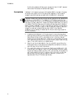
If the AT-3012T repeater is to be connected to an external transceiver,
attach an AUI cable to the 15 pin connector on the back panel. Ensure that
the external transceiver has its Signal Quality Error (SQE)/Heartbeat
!
Attention
Note
Note


