Installation
6
Test function disabled. When power is applied to the AT-3012T repeater
the external transceiver should also have power.
Connections
10BASE-T UTP cables can be up to 100 meters (328 ft.) in length. The cable
should be 22 to 26 AWG UTP wire with 100
Ω
impedance. The AT-3012T
repeater uses RJ45 modular connectors for it’s 10BASE-T connections.
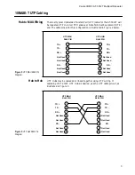
10BASE-T RJ45 wiring may have two connector pinouts. The AT-3012T RJ45
connector is wired as MDI-X. The 10BASE-T UTP cable should be wired
straight through, pin 1 to pin 1, etc., if the device at the opposite end is an MDI
interface. Typically, 10BASE-T transceivers Media Attachment Unit (MAU)
or 10BASE-T host interface cards are wired as Media Dependent Interface
(MDI) interfaces. 10BASE-T Hubs or repeaters are typically wired as MDI-X
interfaces. If the AT-3012T repeater is to be “cascaded” to another 10BASE-T
repeater, a crossover cable may be required. Refer to the Chapter 1
(10BASE-T UTP Cabling) of this manual for the correct wiring pinouts for
Hub to Hub cables.
1.
Attach an RJ45 10BASE-T UTP cable to port 1. Check the respective
ports segment partition switch located on the front panel. The slide switch
should be set to the LEFT, Auto position. Port 1 Link LED should
illuminate provided the 10BASE-T transceiver on the opposite end of the
UTP segment is operational. If not, ensure that the proper cable is being
used or refer to the section on troubleshooting.
2.
Place the AUI port and 10BASE-T port 1 Auto/Off Line switch on the
front panel into the Auto position and establish a connection to a host or
device through the external transceiver.
3.
If no external transceiver is to be used, attach a second 10BASE-T UTP
RJ45 connector to 10BASE-T port 2. Check the Segment partition switch
for port 2 and ensure that it is in the LEFT, Auto position. If not, place the
port 2 slide switch to the LEFT position. Port 2 Link LED on the back
panel should now illuminate provided the 10BASE-T device on the
opposite end of the UTP cable is operational.
Note

