Glossary
18
MANAGEMENT AGENT
—Software that is used to view hub activity and
set hub variables.
MAU
—See Medium Attachment Unit
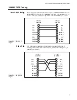
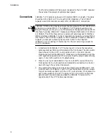
MAU to MAU, HUB to HUB WIRING
—10BASE-T MAU to MAU or hub
to hub wiring generally requires a cross-over cable located somewhere along
the UTP cable run. This may commonly occur at the punch-down block or
between the RJ45 wall receptacle and the workstation.
MAU/TRANSCEIVER
—An Ethernet transceiver is a MAU. A 10BASE-T
MAU interfaces the UTP media to an AUI port on a workstation, repeater,
bridge, or other Ethernet devices.
MDI
—See Medium Dependent Interface
MEDIUM ATTACHMENT UNIT (MAU)
—In a LAN, a device used in a
data station to couple the DTE to the transmission medium.
MEDIUM DEPENDENT INTERFACE (MDI)
—The mechanical and
electrical interface between the trunk cable medium and the MAU.
N-SERIES
—A barrel shaped, threaded connector used on 10BASE5 (thick
Ethernet) coaxial cable.
PATCH PANEL
—A 10BASE-T patch panel may be between a punch-down
block and UTP workstation. The patch panel generally has a female RJ45
connector on the front for each workstation and a Telco (RJ21) connector on
the back, which are wired to a punch-down block. This provides a convenient
way for the installer or network manager to connect the hub 10BASE-T ports
into the desired building locations.
PHYSICAL MEDIUM ATTACHMENT (PMA)
—The portion of the MAU
that contains the functional circuitry.
PHYSICAL SIGNALING (PLS)
—That portion of the physical layer
contained within the DTE that provides the logical and functional coupling
between MAU and data link layers.
POLARITY CORRECTION
—Many 10BASE-T UTP ports have a Polarity
Correction function. If the UTP wiring has RD- and RD+ inadvertently
crossed, the polarity correction function will sample the signal and electrically
swap the wires. If the TD- and TD+ wires are crossed, the correction would
occur at the MAU on the other end of the UTP link. This occurs within a
single pair and should not be confused with the cross-over cable.
PROPAGATION DELAY
—The time it takes a signal to travel from the
input of a system component to the output. Usually measured in nanoseconds.
IEEE 802.3 has specific propagation delay maximums for computing
propagation budgets when designing a LAN. Cable length plays a major role
in propagation delay. [i.e, a 50 meters (164 ft.) AUI cable has a maximum
allowable propagation delay of 257 ns.] The propagation delay of cable is
dependent on length and velocity factor of the cable type. There are also
propagation delays associated with electronics attached to the system.

