4-4
Configuring the Scanner
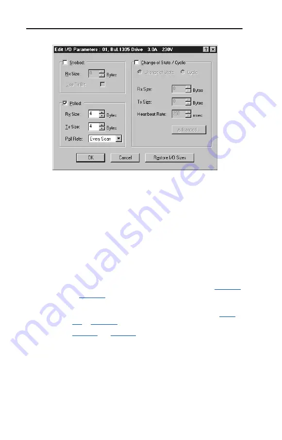
Figure 4.4 Edit I/O Parameters Dialog Box
8.
Select the type(s) of data exchange (Polled, Change of State, and /or
Cyclic). In our example, we selected Polled.
9.
Type the number of bytes that are required for your I/O in the Rx
Size and Tx Size boxes. The size will depend on the following:
•
I/O that you enabled in the adapter. This information can be
found in
Parameter 14 - [DPI I/O Active]
in the adapter.
•
Size of the Reference/Feedback and Datalinks in your drive. This
information can be viewed using
Parameters 07 - [Ref/Fdbk
Size]
and
08 - [Datalink Size]
in the adapter. A 16-bit word is
two bytes, and a 32-bit word is four bytes.
•
The actual size value used in the Rx Size box can be determined
by the setting of the M-S Input parameter as shown in
or
•
The actual size value used in the Tx Size box can be determined
by the setting of the M-S Output parameter as shown in
•
and
show common configuration Tx/Rx
sizes.
In our example, we typed 4 in the Rx Size and Tx Size boxes because
we enabled only the Logic Command/Status for I/O in the adapter
and our drive uses a 16-bit Reference/Feedback.
Both the M-S Input and M-S Output parameters are set to 00001.
Therefore, the Logic Command/Status uses 2 bytes and the
Reference/Feedback uses 2 bytes totaling 4 bytes.
Summary of Contents for PowerFlex 20-COMM-D
Page 1: ...DeviceNet Adapter 20 COMM D FRN 1 xxx User Manual...
Page 6: ...iv Table of Contents Notes...
Page 72: ...6 14 Using Explicit Messaging Notes...
Page 90: ...B 8 Adapter Parameters Notes...
Page 122: ...C 32 DeviceNet Objects Notes...
Page 132: ...E 8 Master Slave I O Configuration Notes...
Page 148: ......


