


Publication 1794-6.5.11 - November 1997
How Communication Takes Place and I/O Image Table Mapping with the DeviceNet Adapter
5
-3
System Throughout
System throughput, from frequency input to backplane, is a function of:
•
the configured minimum frequency sample time
•
the number of channels actually configured for connection to a
specific sensor (0 or 1)
You can set the minimum frequency time during module configuration.
The selection influences the sample data rate, thus affecting system
throughput.
The number of channels included in each input scan also affects system
throughput.
Mapping Data into the
Image Table
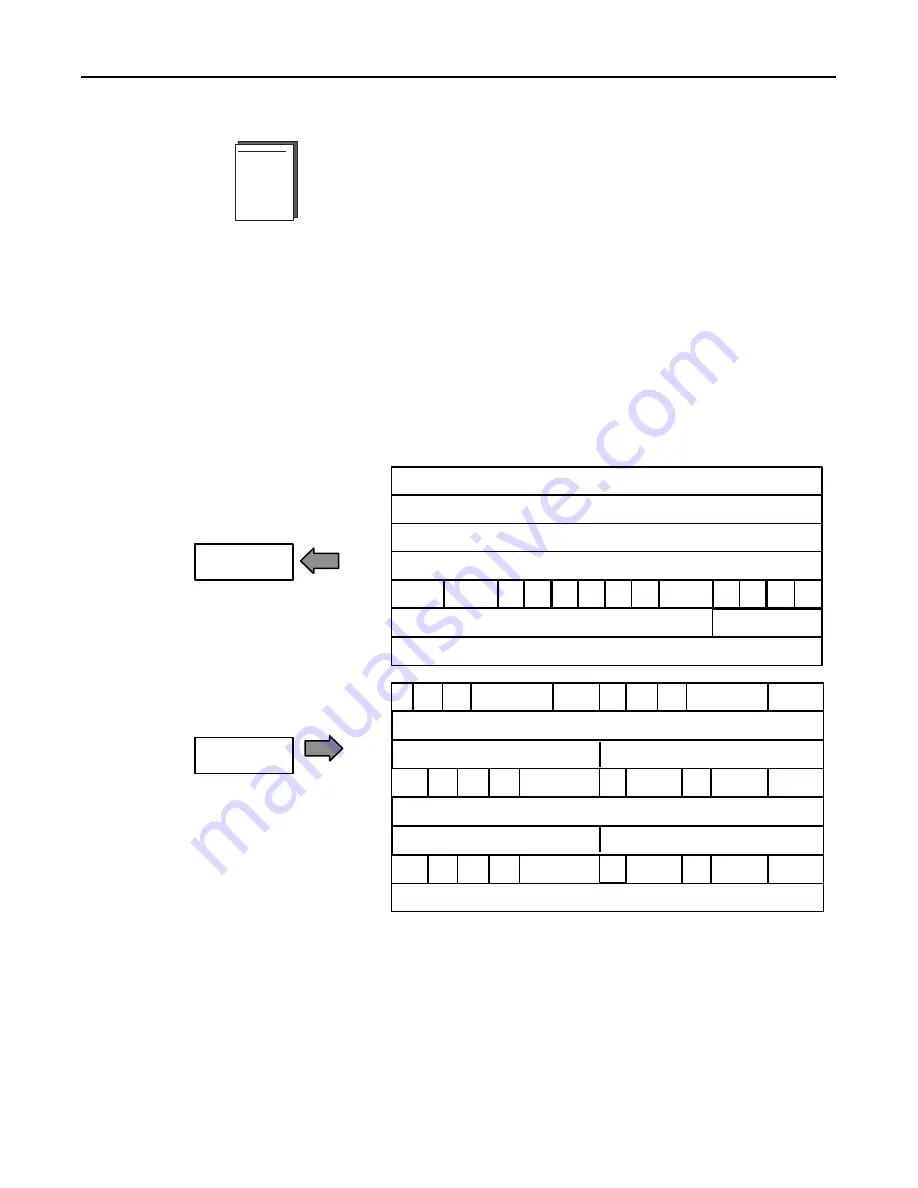
FLEX I/O frequency input module data table mapping is shown below.
Frequency Input Analog Module (1794-IJ2) Image Table
Mapping
Module Image
I/O Image
Input Size
Output Size
0 to 8 Words
1 to 7 Words
Reserved
Reserved
Frequency Channel 0
% Full Scale or Acceleration Channel 0
Diagnostics
Frequency Channel 1
% Full Scale or Acceleration Channel 1
GS
1
F/A
1
WO
1
MPA
1
DIR
1
GS
0
F/A
0
WO
0
MPA
0
DIR
0
R
R
R
Reserved
FR
1
MPM
1
R
NOPTS
1
LF
FR
0
MPM
0
NOPTS
0
SSM
CF
Minimum Freq or Absolute Value of Acceleration Channel 0
Frequency Scaling Divisor Channel 0
Frequency Scaling Multiplier Channel 0
F/A
AS0
WOFM
0
IS
UP0
MPDM
0
MFST
0
ACT 0
IFI
0
IGI
0
WOFF
0
WOFG
0
Minimum Freq or Absolute Value of Acceleration Channel 1
Frequency Scaling Divisor Channel 1
Frequency Scaling Multiplier Channel 1
F/A
AS1
WOFM
1
IS
UP1
MPDM
1
MFST
1
ACT 1
IFI
1
IGI
1
WOFF
1
WOFG
1