0÷5 mm
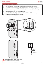
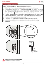
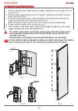
Fig. 2
Fig. 1
Fig. 3
N° 4 Ø 3
P
C1R
51
61
16.5
- 16 -
INSTALLATION
PAIR OF DOOR STATUS CONTACTS
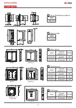
1. Place the door side Door Status device in position, making sure the red cable C1R is at
the top (Fig. 1).
2. Place the frame side Door Status device in position, making sure the letter P (positive
pole) is at the top (Fig. 1).
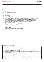
3. By turning the adjusting screws, adapt the position of the Door Status device to the
clearance between the door leaf and the frame (Fig. 2)
N.B.:
the door and frame must not touch as the contacts connect magnetically.
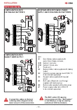
4. Position the Door Status device as shown in Fig. 3.
5. Whenconfiguredwithmainspowersupplyandrechargeablebatteries,usethepower
supply recommended by the manufacturer only.
The electric cable which connects the power supply to the Door Status device
must respect the polarity indicated on the Door Status device with the P for
“positive” at the top .
If the polarity is not respected, the rechargeable batteries will not charge
When configured with rechargeable batteries, the initial total voltage of the battery
pack must be greater than 12 volt, otherwise the batteries will not charge.


