W 3 2 S E R I E S
H I G H P R E S S U R E B R E A T H I N G A I R C O M P R E S S O R
©ALKIN COMPRESSORS
56
2.5.6 Piston ring replacement
The high-pressure stage rings (3rd) wear faster than the other stages. You may need to replace the 3rd stage
piston rings earlier than the other stages. If this will be the case, it is recommended that all piston rings on a
specific piston be replaced at the same time. To remove and replace rings observe the following procedure:
1.
To replace piston rings on the 1st stage piston, both the cylinder and piston are to be removed from the
compressor.
2.
To replace piston rings on the 3 rd stage steeple piston only the compression cylinder need be removed.
Remove the cylinders in the manner outlined in “
Cylinder replacement
” section.
3.
Remove the old piston rings off the 1st and 2nd stage piston.
4.
Remove the rings from the 3rd stage piston in the same manner as on the 1st and 2nd stages.
5.
With the rings removed, thoroughly clean the pistons by brushing or scraping lightly. Pay particular
attention to cleaning the piston ring grooves, oil return holes and gasket seating surfaces on the cylinder.
6.
Inspect the cylinder bore for scoring or scuffing. If the cylinder bore shows signs of being scored or
worn (as indicated by a visible ridging at the end of ring travel.) it must be replaced to establish effective
oil control.
7.
Inspect the piston for signs of excessive scoring or cracking. Particularly check the condition of the ring
grooves for wear on the sides of the ring lands. If any of these conditions are observed, the piston(s)
should be replaced.
8.
To replace the rings of the 1 st and 2 nd pistons, or 3 rd stage steeple piston, lubricate the ring grooves
and replace the rings with a piston ring expander to avoid breakage and distortion. Pay particular
attention to install the rings with the marks facing the appropriate direction into the proper grooves.
9.
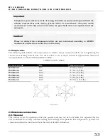
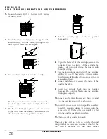
Work from bottom compression ring up on the top end of the piston and from the compression ring
down on the lower end. Observe this drawing to see the manner, which the tapers are to be positioned.
The word “top”, a white dot or similar marking must face the compression chamber. Caution then must
be exercised in placement of the rings labeled on the second stage piston. The three bottoms rings on the
leftmost figure shows the 2nd stage compression rings, which will have its “top” mark facing the
crankcase. On the second figure from left, the ring marking will face away from the crankcase.
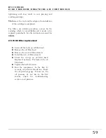
The oil rings on the first and second stages are four piece oil wiper rings with an expanderseparator and two
steel rails. See second figure from left (above). Place the expander and make certain that these ends do not
overlap accidently when installing the other ring segments. Next, install one of the steel rails in the bottom of
the groove; this will hold the expander in place.
Now install the separator on top of the steel rails and over the expander. Make certain the butt ends of the
expander and the end gap of the separator are 180º apart. The second steel rail may now be installed in the top
of the ring groove over the separator. With all rings installed, stagger the end gaps
10.
When new piston rings are to be installed in the original cylinder of the 1 st or 2 nd stage, the cylinder
bore must be “deglazed” to provide a proper seating surface for the
rings. Use a 80 grit abrasive cloth
and go over the cylinder bore using a rotating, reciprocating motion. Do not overdo “deglazing”; dulling
the glaze is usually sufficient and can be accomplished with light pressure.

