9
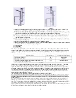
Table 2: Insulation thickness for the part of the system that passes through wall or roof
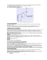
First of all, it is necessary to provide PERFECT CIRCULATION of air (draught) in the flue pipe which must be free
of any obstacles such as narrowing or angles. Any shifts of the axis must have one path inclined with a maximum
angle of 45 degrees from the vertical, and the best solution is 30 degrees. These shifts should be best performed
near the wind resistant top of the chimney.
In accordance with
regulations (the wind resistant top of the chimney, distances and stove placing),
the
distances shown in Table 3 must be met:
Roof
inclination
Distance between the roof ridge cover and the
chimney
Minimum height of the chimney measured at
the upper opening (at the chimney outlet)
α
Distance in meters
Height in meters
15
0
Less than1.85 m
More than 1.85 m
0.50 above the roof ridge cover
1.00 meter from roof pitch
30
0
Less than 1.50 m
More than 1.50 m
0.50 above the roof ridge cover
1.30 meters from the roof pitch
45
0
Less than 1.30 m
More than1.30 m
0.50 above the roof ridge cover
2.00 meters from the roof pitch
60
0
Less than 1.20 m
More than 1.20 m
0.50 above the roof ridge cover
2.60 meters from the roof pitch
Table 3
However, it is obligatory to provide an initial vertical extension (elongation) of 1.5 m (minimum) in order to
provide a proper smoke discharge.
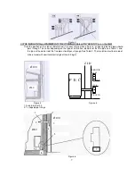
3.4 THE INTAKE OF COMBUSTION AIR (Figure 8)
The air necessary for combustion, taken from the surroundings, must be regenerated through a ventilation grid
located on the wall of the room and turned outwards. This will provide a better combustion and a lower consumption
of biofuel pellets. It is not recommendable that external air is sucked directly through the pipe, because it would
decrease the efficiency i.e. performance of combustion. On its external side, the ventilation opening must be
equipped with a ventilation grid as protection against rain, wind and insects.
This opening must be made on the external wall of the room in which the stove is located.
The intake, i.e. supply of combustion air from garages, warehouses for combustible materials or fire hazard
rooms, is prohibited.
The hole, i.e. opening for external input combustion air
must not be connected
with the use of pipes.
If the room also has any other heating equipment, the intake of combustion air must provide the amount of
air necessary for the proper operation of all the devices.
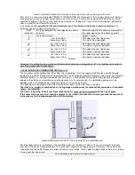
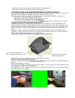
Figure 8.Minimum distances for the installation of the ventilation grid
For the proper and safe installation of the ventilation grid, see the data in Table 4. These are minimum distances
form any air space or smoke discharge. This value can change the configuration of air pressure. These distances
should correspond to the sequence in order to ensure, for example, that an open window intakes external air, taking
it away from the stove itself.
The ventilation grid must be installed at least


