04 * GB_neu.qxp 08.06.2005 9:39 Uhr Seite 2
7
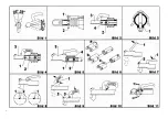
fitting bolt (Fig 2 / Item1). Leave bolts for centring the
shock absorber in the draw bar tube.
Push the ball type coupling and if necessary the
spacer hoop (Fig 5 /Item 4) on the draw bar, so that
the fastening drill holes match. Position distance
bush.
Punch the hexagonal screw M12 x75/80 (Fig 2/Item
2) using the fitting bolt. (Shock absorber is threaded
on).
Insert the second hexagonal screw M12 x75/80 (Fig
2/Item 4).
ATTENTION:
To ensure that the shock absorber is
threaded on, push the draw bar in and out.
If resistance can be felt, the shock absorber is hung
in position.
Screw self-locking hexagonal nuts (use new nuts
supplied) on the screws and tighten using tightening
moment (see table).
Note:
Where there is a cross union a profile disk (Fig
3 / Item1) must be included with the vertical screw.
ATTENTION:
Self-locking nuts may only be used
once.
Shock absorber NOT hung on the fixing bolt.
Slacken and remove self-locking nuts for the
hexagonal bolts. Pull hexagonal bolts out; lift off old
ball type coupling. Push ball type coupling onto the
drawbar so that the fastening drill holes match with
one another. Put distance bush in place (Fig 5).
Insert hexagonal bolts M12x75/80 (Fig 4/Item 1 and
2) and thread distance bush on with them.
Screw self-locking hexagonal nuts on the screws and
tighten using tightening moment (see table).
ATTENTION:
Where there is a cross union a profile
disk (Fig 3 / Item1) must be included with the vertical
screw.
ATTENTION:
Self-locking nuts may only be used once.
TIGHTENING MOMENT:
* Screw quality 8.8 ** AE = overrun device
Operation
for model AK 160/ AK 300/ AK 350:
Swivel range:
Keep swivel range of vertical
±
25
°
(Fig. 1).
Keep swivel range of horizontal
±
20
°
(Fig. 1).
ATTENTION:
If this is exceeded the components will
be overloaded. Function is no longer ensured!
Coupling in place:
Open the ball-type coupling drawbar = to do this, pull
the coupling handle upward in the direction of the
arrow (Fig 7/Item.1). The coupling mechanism has
an “open position”, i.e. as long as the coupling is not
placed on the ball, the coupling handle remains open.
Place the opened ball type coupling drawbar on the
trailer ball of the towing vehicle.
The tongue load causes the ball type coupling
drawbar to lock into place into the starting position
with an audible sound automatically.
For safety reasons also push the handle down
manually (Fig 7 / Item 1).
It is locked and secured automatically.
The trailer ball is coupled correctly when the trailer
device pushes out the green cylinder of the locking
display and the green cylinder becomes visible (Fig 7
/ Item 2).
The coupling mechanism is locked correctly when the
coupling handle can no longer be pushed down by
hand.
ATTENTION: If the ball type coupling drawbar is no
longer coupled to the trailer ball, the trailer can
detach itself from the towing vehicle.
Uncoupling:
Open the coupling handle and lift the ball type
coupling drawbar up on the trailer coupling on the
towing vehicle.
Lifting up and off where there are larger tongue loads
can be made easier by using a jockey wheel.
Wear display:
A wear display on the coupling handle (Fig, 8) shows
if the wear limit of the trailer ball of the towing
vehicle, or the trailer coupling has been reached or
not.
To do this couple the ball type coupling drawbar to
the towing vehicle and drive approx. 500 m with the
car & trailer. The driving movement will give the
coupling mechanism maximum reset. Finally check
the wear as follows.
If the green display is visible on the coupling handle
when coupled (see Fig 8 / Item 2) the ball type
coupling drawbar in its new state or the wear in the
trailer ball is within the permitted boundary/ies.
If the green display on the coupling handle is
completely covered when coupled and only the red
display is visible (Fig 8/Item 1) then the causes are as
follows as a rule:
• Trailer ball in the bottom most wear boundary Ø 49
or less - ball type coupling drawbar without wear.
• Ball type coupling drawbar and trailer ball show
wear.
Overrun device model**
Tightening moment*
AL-KO 60S/2
60 Nm
AL-KO 90S/3
70 Nm
all other overrun devices
86 Nm
AL-KO 2,8VB/1
210 Nm
Summary of Contents for 605 363
Page 1: ...605 363 Zugkugelkupplung DK RUS I H SLO F LT N LV S CZ D NL EST SK GB FIN P E PL GR f...
Page 3: ...1...
Page 45: ...2 4 43...
Page 49: ...2 4 47...
Page 53: ...2 4 1 51...
Page 57: ...8 1 55 2 4...
Page 61: ...2 4 59...
Page 63: ...50 30 RUS_neu qxp 08 06 2005 11 21 Uhr Seite 4 61...
Page 65: ...2 4 63...
Page 69: ...2 4 67 67...
Page 73: ...2 4 71...
Page 77: ...2 a 4 75...
Page 81: ...2 4 79...
Page 85: ...2 4 83...
Page 87: ...AL KO AL KO 371 912 ETI 50mm GR_neu qxp 08 06 2005 11 31 Uhr Seite 5 85...


