Hardware resources
akYtec GmbH · Vahrenwalder Str. 269 A · 30179 Hannover · Germany Tel.: +49 (0) 511 16 59 672-0 ·
14
NOTICE
If the input signal does not correspond with the hardware configuration, the device
can be damaged. Check the positions of the jumpers XP
1…XP4 before wiring.
To configure the input hardware:
– remove the front cover
– set the jumpers on the respective jumper block XP in accordance to the expected
input signal using a thin tool (e.g. tweezers)
– close the front cover.
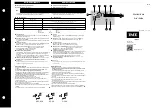
Fig. 4.4 Input jumper positions
a) 0-10 V, b) 4-20 mA, c) digital mode, d) 0-4000 ohm
The lower and upper measuring limits must be set to scale the input signal.
Scaling is not available if the signal 0-4000 ohm is selected. In that case the measured value
is represented only in REAL32 format. The parameter
Decimal places
(
DP
) is not available
for 0-4000 ohm signal as well.
The resistance input is designed for 2 wire sensors only.
The effect of lead resistance can be compensated in the program.
4.1.2
Digital mode
Configurable parameters:
Input mode
– select
Digital
Filter
– filter time constant (0…60 s)
Logical 0
– 0…10 V
Logical 1
– 0…10 V
The input operates as a comparator with parameters
Logical 0
and
Logical 1
which
determine the hysteresis and
can be set in the range of 0…10 V (Fig. 4.5).
Fig. 4.5 Digital mode operation
4.1.3
Analog input filtering
The input filter stabilizes the input reading. The filter setting is a time constant representing
the time interval in which the signal reaches 0.63 of the measured value. It can be set within
the range of 0.01…60 s with the increment of 0.001 second for each input separately.
The greater the time constant, the higher the damping of the interference signal and the
slower the reaction to rapid changes in the input value.
4.2
Analog outputs AO1, AO2
The model x.2.x has two analog outputs 4-20 mA, x.4.x has two analog outputs 0-10 V.