H. ZANDER GmbH & Co. KG • Am Gut Wolf 15 • 52070 Aachen • Germany
Tel +49 (0)241 9105010 • Fax +49 (0)241 91050138 •
[email protected] • www.zander-aachen.de
1
Emergency Stop Safety Relay SR7C
M03
Ver. A
E61-141-00
Operating Instructions
English translation
Errors and technical changes reserved
The SR7C is a universal emergency stop safety switching device
with seven safe relay outputs that can quickly and safely stop the
moving parts of a machine or system in case of danger.
Applications for the SR7C include single or dual-channel emer-
gency stop circuits and guard monitoring on machines and sys-
tems.
Function
The emergency stop safety switching device SR7C is
designed for safe isolation of safety circuits according to
EN 60204-1 and can be used up to safety category 4, PL e
according to EN ISO 13849-1.
The internal logical system closes the safety contacts when
the start button is pressed.
If the safety switch is opened, the positively driven safety
contacts are opened and safely switch the machine off. It is
ensured that a single fault does not lead to a loss of the
safety function and that every fault is detected by cyclical
self-monitoring no later than when the system is switched
off and switched on again.
The operating status of the device is indicate by the auxilia-
ry transistor outputs O1 and O2.
O1: Ready. PWR is connected.
O2: Both relay channel K1, K2 are switched on.
Electrical
Connection
•
Consider the information in the section "Techn. data"
•
A safe transformer according to IEC 61558-2-6 or a
power supply unit with electrical isolation from the
mains must be connected
•
External fusing of the safety contacts must be provided
•
If the device does not function after commissioning, it
must be returned to the manufacturer unopened. Ope-
ning the device will void the warranty
•
Use adequate protective circuit for inductive loads (e.g.
free-wheeling diode)
Installation
As per EN 60204-1, the device is intended for installation in
control cabinets with a minimum degree of protection of
IP54. It is mounted on a 35 mm DIN rail according to
DIN EN 60715 TH35.
Safety
Precautions
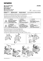
Fig. 1 Block diagramm SR7C
Fig. 2 Installation / removal
Fig. 3 Connections
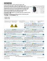
A1:
Power Supply
A2 :
Power Supplay
S11:
DC 24V control voltage
S10:
Control line
S12:
Control line
S13:
Control line
S14:
Control line
S21:
Start, Control line
O1;O2:
Aux transistor outputs
0V:
Reference common O1, O2
81-82:
Auxiliary Contact
91-92:
Auxiliary Contact
101-102: Auxiliary Contact
101-112: Auxiliary Contact
13-14 bis 73-74:
Safety Out1-7
•
All relevant safety regulations and standards are to be
observed.
•
The overall concept of the control system in which the
device is incorporated must be validated by the user.
•
Failure to observe the safety regulations can result in
death, serious injury and serious damage.
•
Note down the version of the product (see label “Ver: x”)
and check it prior to every commissioning of a new de-
vice. If the version has changed, the overall concept of
the control system in which the device is incorporated
must be validated again by the user.
•
Installation and commissioning of the device must be
performed
only by authorized personnel
.
•
Observe the country-specific regulations when installing
the device.
•
The electrical connection of the device is only allowed to
be made with the device isolated.
•
The wiring of the device must comply with the instruc-
tions in this user information, otherwise there is a risk
that the safety function will be lost.
•
It is not allowed to open the device, tamper with the
device or bypass the safety devices.
•
7 safe, redundant relay outputs
•
4 auxiliary relay and 2 auxiliary semiconductor outputs
•
Connection of:
- Emergency stop buttons
- Safety switches
- Non-contact safety switches
- OSSD-Outputs
•
Single or dual-channel operation possible
•
Feedback loop for monitoring downstream contactors or
expansion modules
•
Cyclical monitoring of the output contacts
•
Indication of the swiching state via LED
•
2 start behavior possible:
- Monitored manual start
- Automatic start
•
Up to PL e, SILCL 3, category 4
•
STOP-category: 0
Correct Use