


46
Rev 2.1
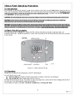
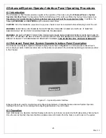
4-4 System Operator Interface Panel Home Page
For System Operator Interface multiple unit applications, each boilers is represented on the Home page by an icon and
name. Pressing the icon allows the user to zoom in on that boiler and see specific details about it. These details are
provided on a new page, which can include additional buttons that display additional detail and operation information,
which itself leads to other pages.
The System Operator Interface
Boiler Icon
button will appear in one of four colors indicating the boiler status.
•
Blue
: Normal operation
•
Red
: Lockout condition
•
Gray
: Standby mode (burner switch off)
•
Gray and crossed out
: Communication error (disconnected or powered off)
Up to 8 boilers can be displayed on the System Operator Interface Home page. The name of each boiler is displayed next
to each boiler icon. When Lead Lag is enabled, the system header temperature and firing rate are displayed for each icon.
When the burner is in standby or not firing the firing rate is not displayed.
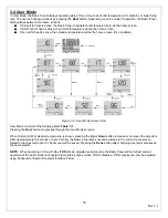
4-5 Page Navigation
The Operator Interface Display presents information and options in a paged manner. Pages are displayed in a tree
structure in which the user navigates up and down to arrive at the desired Function. The page descriptions are provided
below so that you can understand the purpose of each and view the selections, parameters, and information that is
available or required on each.
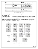
Most pages have a
Home
button in the top-left corner of the screen and a
Back
button in the top-right corner of the
screen.
•
The
Home
button returns the user to the Home page and terminates any operation in progress.
•
The
Back
button returns the user to the previous page.
Two other icons may be noticed near the boiler name.
•
A
Bell
will be displayed if the system is in Lockout that reset will be required.
•
A
Padlock
will be shown on screens that a password is needed to change the parameter. An unlocked padlock
indicates the password has been entered to change the parameter depending on the security level entered.
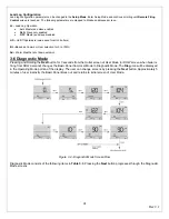
4-6 Keyboard
Some pages request user entry of characters. When this type of input is required, a Keyboard Page
appears, as shown
Figure 4.4
. The text box at the top of the screen displays the current or default setting of the user input. The user can add
to this text, clear it, or change it.
The
Shift
key on the left side of the screen shifts between upper and lowercase characters. Pressing the
Shift
key
toggles the keyboard from one mode to the other. The
OK
button should be pressed when the user is done entering the
text input. The
Cancel
button on the bottom of the screen allows the user to ignore any text changes that have been
made and keep the original text value. Pressing the
OK
or
Cancel
buttons returns the user to the page displayed prior to
the keyboard page.
Summary of Contents for A050-A300
Page 28: ...28 Rev 2 1 ...
Page 31: ...31 Rev 2 1 Figure 2 10 One Atlas One Tank Suggest Piping Diagram ...
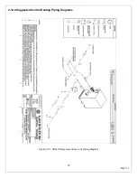
Page 32: ...32 Rev 2 1 Figure 2 11 One Atlas Two Tank Piping Diagram ...
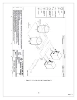
Page 33: ...33 Rev 2 1 Figure 2 12 Two Atlas One Tank Piping Diagram ...
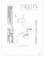
Page 34: ...34 Rev 2 1 Figure 2 13 Two Atlas Two Tank Piping Diagram ...
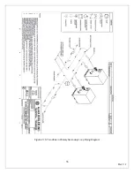
Page 36: ...36 Rev 2 1 Figure 2 15 Two Atlas in Primary Secondary Loop Piping Diagram ...
Page 113: ...113 Rev 2 1 ...


