


41
Rev 2.1
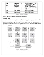
Lead Lag Configuration
Lead lag configuration parameter can be changed in the
Setup Mode
. Enter Setup Mode and continue scrolling until
Remote Firing
Control
screen is reached. The following parameters are mapped to Modbus addresses screen.
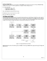
LL -
Lead Lag Operation
•
Ldr
: Master and slave enabled
•
SLA
: Slave only enabled
•
OFF
: Master and slave disabled
HS –
On/Off Hysteresis (value used for all LL boilers)
BL –
Baseload Common (User selection for 0 to 100%)
Sd –
Warm Weather shut down setpoint
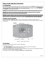
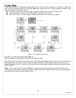
3-6 Diagnostic Mode
Pressing and Holding the
Next
button for 3 seconds from the Outlet screen of User Mode (or DHW screen when boiler is
firing from DHW demand) changes the Basic Panel from User Mode to Diagnostic Mode. The
Diag
icon will be displayed
in the Operating Mode portion of the display. The user can change screens by pressing the
Next
button. Approximately 5
minutes of user inactivity the Basic Panel times out and returns to initial screen of User Mode.
Figure 3.4 - Diagnostic Mode Screen Flow
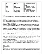
Diagnostic Mode consists of the following items in
Table 3.3
. Pressing the
Next
button progresses through the Diagnostic
Mode screens
Summary of Contents for A050-A300
Page 28: ...28 Rev 2 1 ...
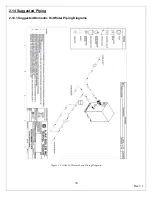
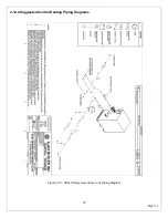
Page 31: ...31 Rev 2 1 Figure 2 10 One Atlas One Tank Suggest Piping Diagram ...
Page 32: ...32 Rev 2 1 Figure 2 11 One Atlas Two Tank Piping Diagram ...
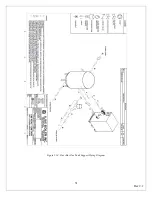
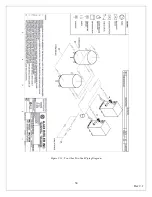
Page 33: ...33 Rev 2 1 Figure 2 12 Two Atlas One Tank Piping Diagram ...
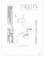
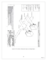
Page 34: ...34 Rev 2 1 Figure 2 13 Two Atlas Two Tank Piping Diagram ...
Page 36: ...36 Rev 2 1 Figure 2 15 Two Atlas in Primary Secondary Loop Piping Diagram ...
Page 113: ...113 Rev 2 1 ...


