53
Rev 2.1
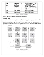
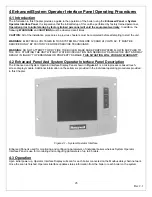
Figure 4.17 – Honeywell Sola Controller Alert Log
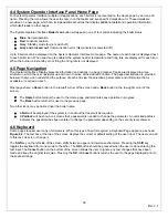
4-13 Operation Page
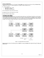
The Operation Page displays the boiler running operation, including setpoint and firing rate. From this page the user can
change setpoints, view annunciation information, and switch between Central Heating or Domestic Hot Water loops, as
shown in
Figure 4.20
. If a password is required to change any of the settings on this page, the user can press the
Login
button to enter the password.
Figure 4.20 – Honeywell Sola Controller Operation Page
4-14 Diagnostic Page
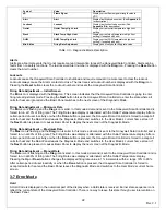
The Diagnostic Page displays analog and digital I/O status of the Honeywell Sola Controller. A snapshot of the diagnostic
status is displayed and updated once per second as it changes in the Honeywell Sola Controller.
See
4-36 HONEYWELL SOLA CONTROLLER DIAGNOSTICS
for more information.
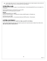
The digital I/O data is displayed as LED that are either on
Green
light or off
Red
light. Not all digital I/O can be displayed
at the same time on the page, so a horizontal scroll bar is used to move the view left and right to show all digital I/O data.
Honeywell Sola Controller’s analog I/O can also be viewed on the Operator Interface. A snapshot of the diagnostic status
is displayed and updated as it changes in the Honeywell Sola Controller.
The analog I/O data is displayed as bar charts with the I/O level represented in the I/O. Analog I/O that is not enabled for
the installation displays a blank I/O level. Not all analog I/O can be displayed at the same time on the page, so a
horizontal scroll bar is used to move the view left and right to show all analog I/O status.
A
Diagnostic Tests
button allows the user to conduct different diagnostics on the Honeywell Sola Controller.
See
4-37
INSTALLER CHECKOUTS – DIAGNOSTICS TESTS
for more details.
Summary of Contents for A050-A300
Page 28: ...28 Rev 2 1 ...
Page 31: ...31 Rev 2 1 Figure 2 10 One Atlas One Tank Suggest Piping Diagram ...
Page 32: ...32 Rev 2 1 Figure 2 11 One Atlas Two Tank Piping Diagram ...
Page 33: ...33 Rev 2 1 Figure 2 12 Two Atlas One Tank Piping Diagram ...
Page 34: ...34 Rev 2 1 Figure 2 13 Two Atlas Two Tank Piping Diagram ...
Page 36: ...36 Rev 2 1 Figure 2 15 Two Atlas in Primary Secondary Loop Piping Diagram ...
Page 113: ...113 Rev 2 1 ...

