20
Rev 2.1
Vertical Venting (Category IV)
The maximum and minimum venting length for this Category IV appliance shall be determined per the NFGC (US) or
CGA, B149 (Canada).
The diameter of the vent flue pipe should be sized according to NFGC (US) and Appendix B of the CGA, B149 (Canada).
The minimum flue diameter for conventional venting using Category IV, stainless steel AL29-4C vent is:
6 inches for Models A050 – A075
8 inches for models A100 – A150
10 inches for model A200
12 inches for models A250 – A300
The connections from the appliance vent to stack must be as direct as possible and shall be same diameter as the vent
outlet. The horizontal breaching of a vent must have an upward slope of not less than ¼" per linear foot from the boiler to
vent terminal. The horizontal portions of the vent shall also be supported for the design and weight of the material
clearances and to prevent physical damage or separation of joints.
Note:
A vent adapter (field supplied) may be required to connect the Category IV vent to the boiler.
Termination
The vent terminal should be vertical and should terminate outside the building at least 2ft above the highest point of the
roof that is within 10ft. The vent cap should have minimum clearance of 4ft horizontally from, and in no case above or
below (unless a 4ft horizontal distance is maintained), electric meters, gas meters, regulators and relief equipment. The
distance of the vent terminal from adjacent public walkways, adjacent building, open windows and building opening must
be consistent with the NFGC (US) or CGA, B149 (Canada). Gas vents supported only by flashing and extended above the
roof more than 5ft should be secured by guy-wires or braced to withstand snow and wind loads.
Caution:
A listed vent cap terminal suitable for connection to the Category IV vent materials, adequately sized, must be
used to evacuate the flue products from boilers.
Common Venting
The NFGC does not address sizing guidelines for the common venting of multiple Category IV boilers. When common
venting multiple units together, the venting must be designed by a professional engineer to ensure the chamber pressure
of each boiler is always below 0.5” w.c. at high fire.
Warning:
Vent connectors serving any other appliances shall not be connected into any portion of the mechanical draft
systems operating under positive pressure. If an Ajax boiler is installed to replace an existing boiler, the vent system must
be verified to be of the correct size and of Category IV AL29-4C vent material.
If it is not, it must be replaced
.
2-7 Gas Supply
Danger:
Make sure the gas on which the boiler will operate is the same as that specified on the boiler rating plate (natural
gas/propane).
The gas line should be a separate line running directly from the gas meter to the unit, unless the existing gas line is of
ample capacity. Verify the capacity of the existing gas piping if it is to be used.
The gas pipe must have a sediment trap ahead of the boiler connection controls and a manual shut – off valve (one set for
each fuel source if using an Atlas Combination Fuel Unit) located outside the boiler cabinet. It is highly recommended that
a union be installed in the gas supply line adjacent to the boiler for serving (see diagram below). The maximum working
gas pressure for both natural gas and propane is 14" w.c. Keep in mind that an increase the gas pressure, without
making additional adjustments, leads to an increased BTU input and a decreased efficiency.
Caution:
If the gas pressures exceed 14" w.c., a gas pressure regulator must be installed prior to the gas connection to
reduce the supply pressure.
WARNING:
A sediment trap MUST be installed on the gas piping for each gas line.
Summary of Contents for A050-A300
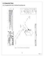
Page 28: ...28 Rev 2 1 ...
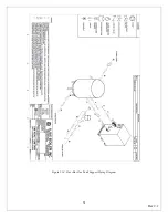
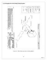
Page 31: ...31 Rev 2 1 Figure 2 10 One Atlas One Tank Suggest Piping Diagram ...
Page 32: ...32 Rev 2 1 Figure 2 11 One Atlas Two Tank Piping Diagram ...
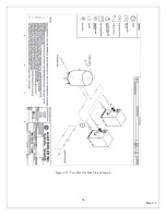
Page 33: ...33 Rev 2 1 Figure 2 12 Two Atlas One Tank Piping Diagram ...
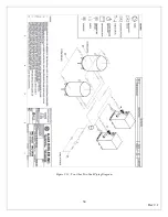
Page 34: ...34 Rev 2 1 Figure 2 13 Two Atlas Two Tank Piping Diagram ...
Page 36: ...36 Rev 2 1 Figure 2 15 Two Atlas in Primary Secondary Loop Piping Diagram ...
Page 113: ...113 Rev 2 1 ...


