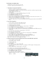
25
6. UTCO (User TOC) Deleting Procedure
If “UTCO ERROR” or other message is displayed when inserting recorded disk and the UTCO needs to be deleted, follow
this procedure.
1)
Insert the disk whose UTOC is to be deleted.
2)
Use the B.SKIP button and F.SKIP button to move the pickup to the center of the disk.
3)
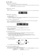
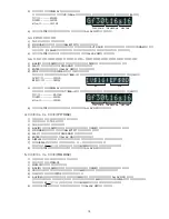
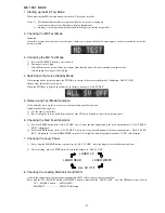
Press the MD MODE button to display “SELECT GRV”.
4)
Press the MD REC button to display “REC Analog”
5)
Press the PLAY button to display “FOCUS ON!”.
6)
Press the ENTER button to display “ALL SV ON”.
7)
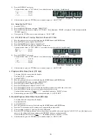
Press the TAPE REC/REC MUTE button to display “UTOC ERASE”.
8)
After deleting the UTOC, the display automatically returns to “ALL SV OFF”.
7. Initializing Procedure of EEP-ROM
Follow the procedure given below to set the adjustment value of EEP-ROM to the default value (reference value).
1)
While pressing the CD OPEN/CLOSE button, press the MD EDIT button of the unit.
2)
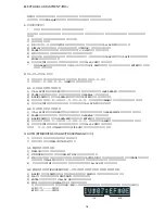
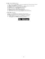
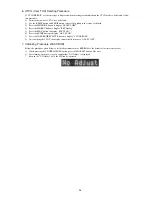
After turning on the power again, confirm that “NO Adjust” is displayed.
*
Even in the “NO Adjust” state, the MD can be operated.
Summary of Contents for XR-MD510
Page 5: ... 5 ...
Page 15: ... 15 SCHEMATIC DIAGRAM 1 MAIN PT1 PT2 RELAY ...
Page 17: ... 17 SCHEMATIC DIAGRAM 2 FRONT SW 1 SW 2 FACE A FACE B FACE C DECK ...
Page 20: ... 20 SCHEMATIC DIAGRAM 3 CD CD LOAD CD DRIVE ...
Page 22: ... 22 SCHEMATIC DIAGRAM 4 D TUNER ...
Page 24: ... 24 SCHEMATIC DIAGRAM 5 K TUNER ...
Page 26: ... 26 SCHEMATIC DIAGRAM 6 EZ TUNER ...
Page 29: ... 29 IC BLOCK DIAGRAM IC BA5936S IC BU2099FV ...
Page 30: ... 30 IC BU2092F IC BU1920FS ...
Page 31: ... 31 IC MM1454XFBE IC LA1837NL ...
Page 32: ... 32 IC TA2040AF IC HA12211 ...
Page 33: ... 33 IC CXA1553P IC LC72131D ...
Page 34: ... 34 IC BD3876KS2 ...
Page 38: ... 38 8 SFR130 TP3 VREF TP2 FE C CD C B L201 7 TP1 K SCAN GND IC201 7 B FRONT C B ...
Page 43: ... 43 98 O ARDY O 99 O SREQ O 100 I MREQ I ja ja 01234 ja 0123 fLl ...
Page 55: ... 55 FL 13 ST 44GNK ACJ 4 GRID ASSIGNMENT ANODE CONNECTION GRID ASSIGNMENT ...
Page 56: ... 56 ANODE CONNECTION ...

