13
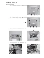
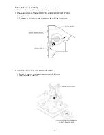
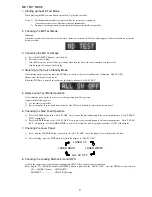
Notes during re-assembling
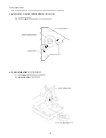
When assemble the magical change panel, adjust the phase of the gear.
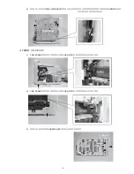
1. Phase adjustment of the GEAR, OPE 1 and GEAR, WORM WHEEL.
1) Align holes
1
.
2) Then, move the position of the holes of each gear as shown by
2
in the illustration.
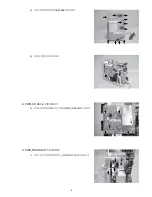
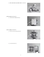
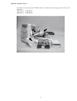
2. Installation Procedure of HLDR, GEAR ASSY
1) Position the panel side so that it faces front as shown in the illustration.
2) Install the HLDR, GEAR ASSY.
Summary of Contents for XR-MD510
Page 5: ... 5 ...
Page 15: ... 15 SCHEMATIC DIAGRAM 1 MAIN PT1 PT2 RELAY ...
Page 17: ... 17 SCHEMATIC DIAGRAM 2 FRONT SW 1 SW 2 FACE A FACE B FACE C DECK ...
Page 20: ... 20 SCHEMATIC DIAGRAM 3 CD CD LOAD CD DRIVE ...
Page 22: ... 22 SCHEMATIC DIAGRAM 4 D TUNER ...
Page 24: ... 24 SCHEMATIC DIAGRAM 5 K TUNER ...
Page 26: ... 26 SCHEMATIC DIAGRAM 6 EZ TUNER ...
Page 29: ... 29 IC BLOCK DIAGRAM IC BA5936S IC BU2099FV ...
Page 30: ... 30 IC BU2092F IC BU1920FS ...
Page 31: ... 31 IC MM1454XFBE IC LA1837NL ...
Page 32: ... 32 IC TA2040AF IC HA12211 ...
Page 33: ... 33 IC CXA1553P IC LC72131D ...
Page 34: ... 34 IC BD3876KS2 ...
Page 38: ... 38 8 SFR130 TP3 VREF TP2 FE C CD C B L201 7 TP1 K SCAN GND IC201 7 B FRONT C B ...
Page 43: ... 43 98 O ARDY O 99 O SREQ O 100 I MREQ I ja ja 01234 ja 0123 fLl ...
Page 55: ... 55 FL 13 ST 44GNK ACJ 4 GRID ASSIGNMENT ANODE CONNECTION GRID ASSIGNMENT ...
Page 56: ... 56 ANODE CONNECTION ...

