background image

9. Appendix 


AirLive SD-2020 User’s Manual


93 

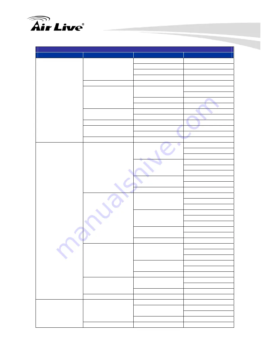
H.264 + H.264 + H.264 + H.264 / MJPEG 

H.264-1 

H.264-2 

H.264-3 

H.264-4 / MJPEG 

640 x 480 (60 fps) 

720 x 480 (60 fps) 

352 x 240 (60 fps) 

640 x 480 (30 fps) 

640 x 480 (60 fps) 

640 x 480 (60 fps) 

352 x 240 (60 fps) 

800 x 600 (60 fps) 

352 x 240 (60 fps) 

352 x 240 (60 fps) 
720 x 480 (60 fps) 

720 x 480 (30 fps) 

640 x 480 (60 fps) 

720 x 480 (60 fps) 

352 x 240 (60 fps) 

720 x 480 (30 fps) 

640 x 480 (30 fps) 

640 x 480 (60 fps) 

640 x 480 (60 fps) 

352 x 240 (60 fps) 

720 x 480 (60 fps) 

352 x 240 (60 fps) 

352 x 240 (60 fps) 

640 x 480 (30 fps) 

640 x 480 (30 fps) 

640 x 480 (60 fps) 

640 x 480 (60 fps) 

352 x 240 (60 fps) 

640 x 480 (60 fps) 

352 x 240 (60 fps) 

352 x 240 (60 fps) 

352 x 240 (60 fps) 

352 x 240 (60 fps) 

352 x 240 (60 fps) 
720 x 480 (30 fps) 
640 x 480 (30 fps) 

800 x 600 (30 fps) 

352 x 240 (30 fps) 
720 x 480 (30 fps) 
640 x 480 (30 fps) 

720 x 480 (30 fps) 

352 x 240 (30 fps) 
640 x 480 (30 fps) 

640 x 480 (30 fps) 

352 x 240 (30 fps) 

1024 x 768 (30 fps) 

352 x 240 (30 fps) 

352 x 240 (30 fps) 
720 x 480 (30 fps) 
640 x 480 (30 fps) 

800 x 600 (30 fps) 

352 x 240 (30 fps) 
720 x 480 (30 fps) 
640 x 480 (30 fps) 

720 x 480 (30 fps) 

352 x 240 (30 fps) 
640 x 480 (30 fps) 

640 x 480 (30 fps) 

352 x 240 (30 fps) 

800 x 600 (30 fps) 

352 x 240 (30 fps) 

352 x 240 (30 fps) 
720 x 480 (30 fps) 
640 x 480 (30 fps) 

720 x 480 (30 fps) 

352 x 240 (30 fps) 
640 x 480 (30 fps) 

640 x 480 (30 fps) 

352 x 240 (30 fps) 

720 x 480 (30 fps) 

352 x 240 (30 fps) 

352 x 240 (30 fps) 
640 x 480 (30 fps) 

640 x 480 (30 fps) 

352 x 240 (30 fps) 

640 x 480 (30 fps) 

352 x 240 (30 fps) 

352 x 240 (30 fps) 

1024 x 768 (30 fps) 

352 x 240 (30 fps) 

352 x 240 (30 fps) 

352 x 240 (30 fps) 

800 x 600 (60 fps) 

352 x 240 (60 fps) 
720 x 480 (60 fps) 

720 x 480 (60 fps) 

640 x 480 (60 fps) 

800 x 600 (30 fps) 

640 x 480 (60 fps) 

640 x 480 (60 fps) 

800 x 600 (30 fps) 

800 x 600 (60 fps) 

720 x 

352 x 

Summary of Contents for SD-2020

Page 1: ...SD 2020 2 Megapixel 20X Optical Zoom Speed Dome IP Camera User s Manual ...

Page 2: ...al photocopying or recording without the written consent of OvisLink Corp OvisLink Corp has made the best effort to ensure the accuracy of the information in this user s guide However we are not liable for the inaccuracies or errors in this guide Please use with caution All information is subject to change without notice All Trademarks are properties of their respective holders ...

Page 3: ...Increase the separation between the equipment and receiver Connect the equipment into an outlet on a circuit different from that to which the receiver is connected Consult the dealer or an experienced radio TV technician for help FCC Caution Any changes or modifications not expressly approved by the party responsible for compliance could void the user s authority to operate this equipment This dev...

Page 4: ...ent 6 2 2 Connections 6 2 3 Mounting the Camera 9 2 4 Connect to IP Camera 11 3 Using IP Camera via Web Browser 15 3 1 Windows Web Browser 15 4 Operating IP Camera via Mobile Phone 17 4 1 Using IP Camera via iPhone 17 5 Configuration of Main Menu 20 5 1 Live View 21 5 2 System 24 5 3 Streaming 24 5 4 PTZ 24 5 5 Logout 24 6 System 25 6 1 System 25 6 2 Security 27 6 3 Network 33 6 4 DDNS 39 6 5 Mail...

Page 5: ...rmation 59 6 16Factory Default 61 6 17Software Version 62 6 18Software Upgrade 63 6 19Maintenance 64 7 Streaming 65 7 1 Video Format 65 7 2 Video Compression 67 7 3 Video OCX Protocol 69 7 4 Video Frame Rate 70 7 5 Audio 71 8 PTZ 73 8 1 Preset 73 8 2 Cruise 74 8 3 Auto Pan 75 8 4 Sequence 77 8 5 Home 78 8 6 Tilt Range 79 8 7 Privacy Mask 80 8 8 Camera Exposure 82 8 9 Camera WB 83 8 10Camera Misc1 ...

Page 6: ...Table of Contents AirLive SD 2020 User s Manual v 8 12Camera Default 89 9 Appendix 90 A Video Resolution 90 B Smart Tracking Optional 99 ...

Page 7: ... electrical source With the IP 66 waterproof housing AirLive SD 2020 suits for environments such as stairs main entrance street and basement The device is accessible via the LAN or Internet connection Connect your device directly to a local area network or xDSL modem and with Microsoft Internet Explorer you get instant on demand video streams Within minutes you can set up the device to capture a v...

Page 8: ...ga Sony CMOS image sensor Sensor Resolution 1920X1080 CS Mount Lens 4 7 94 mm Lens Type F 1 6 Night Vision Yes Max IR Distance None Minimum Illumination 0 05 LUX Mechanical IR Cut Filter Yes Auto Iris Yes Viewing Angle H Wide 55 2 ゚ H F1 6 Tele 5 2 ゚ H F2 8 V Wide 42 1 ゚ H F1 Tele 2 4 ゚ H F2 8 Pan Degree 0 360 Tilt Degree 10 190 Preset Points Up to256 preset point Pan Tile Control Camera Tour Up t...

Page 9: ... date OSD Digital Zoom 10X Audio Encoder G 711 G 726 ADPCM AAC Audio Streaming Two way Audio Audio Input Output Speaker microphone I O port Ethernet 10 100 Mb Ethernet RJ 45 PoE IEEE802 3at Wireless None Supported Protocols IPv4 v6 TCP IP UDP RTP RTSP HTTP HTTPS ICMP FTP SMTP DHCP PPPoE UPnP IGMP SNMP IEEE 802 1x QoS ONVIF Password protection IP filter Security HTTPS Network Users Up to 20 simulta...

Page 10: ...earch Installation IP Wizard II Motion detection Event Triggers External input via DI interface Motion Detection 10 FTP file upload E mail alert HTTP Event handler DO digital output alarm UPNP Yes Open API for software integration Application Programming Interface SDK Video Buffer Pre and post alarm buffering Alarm Triggers Intelligent video motion detection and external input File upload via FTP ...

Page 11: ...ts these minimum requirements for proper operation Item Requirements CPU Pentium 4 3 0 GHz or higher Core2 Duo 2GHz or higher VGA Monitor Resolution1280 x 1024 or higher RAM Minimum 1 GB of RAM 2GB or above is recommended Operating System Window XP Vista or Windows 7 Web Browser Internet Explorer 6 or later Apple Safari Firefox Google Chrome Note Please keep updating the latest Windows software an...

Page 12: ...formation and instructions for installing this device 4 Accessory Package 2 2 Connections Power Source Requirement This camera can work with 802 3at POE switch However if you need to operate this camera below 0 degree Celsius please purchase the optional power adapter for the heater to work Switch Connector There are various connectors located on AirLive SD 2020 s back plate as shown in the figure...

Page 13: ...ra to a 100Mbps Fast Ethernet network switch or hub In the LAN socket there are two LEDs embedded LAN LED green color Green Link Light indicates good network connection Power orange color This LED is used to indicate whether DC power is on or not 2 Alarm I O AirLive SD 2020 supports 4 digital alarm inputs and 2 digital alarm outputs Please make sure the alarm connections are properly wired before ...

Page 14: ...e refer to the illustrations below to connect power core through the supplied power adaptor Note Supply the power to the Network Camera with the power adapter which is Not included in package 4 Audio I O Connectors Please refer to the illustrations below to set up the audio according to the audio pin definition ...

Page 15: ...Button This button is used to restore all the factory default settings Sometimes restarting the device will make the system back to a normal state 2 3 Mounting the Camera 1 Attaching the Standard Mount Kit AirLive ACC WMK SD20 Optional Fix the camera with bundle wall mount kit as below Wall Mounting Follow the steps below to mount AirLive SD 2020 with the Standard Wall Mount ...

Page 16: ...insects entering the Wall Mount z Thread the cable s through the Mounting Kit and join the Mounting Kit to the Standard Wall Mount with the supplied screws and washers Then adjust the Waterproof Rubber to the joint z Connect the cable s to AirLive SD 2020 z Join AirLive SD 2020 to the Mounting Kit with the supplied screw and washers 2 Connecting to LAN A You can use the provided Ethernet cable to ...

Page 17: ...er When the power LED turned on it means that the system is booting up successfully Furthermore if you have a proper network connection and access to the camera the LAN LED green will flash Note Use the 24VAC power adapter which is Not included in the package and connect it to wall outlet for AC power 2 4 Connect to IP Camera 1 Insert the bundle CD into your PC Laptop 2 Auto Run Screen then shows ...

Page 18: ...2 Package Contents and Installation AirLive SD 2020 User s Manual 12 ...

Page 19: ...nts and Installation AirLive SD 2020 User s Manual 13 3 After completing installation run the configuration tool software 4 The Software scans the network and finds the IP Camera and then lists them in the dialog box ...

Page 20: ...Live SD 2020 User s Manual 14 5 If the Camera s IP address is in the same IP segment as your LAN select the founded IP Camera and double click on the item Then the default browser will show up and connect to the IP camera s Web automatically ...

Page 21: ... enter http IP index2 htm as your web URL 2 Use the default account admin and default password airlive Note The default user name admin and the password airlive are set at the factory for the administrator You can change them in the Account Menu Please check System Security User 3 The monitor image will be displayed in your browser In the top side of main configuration are System Streaming and PTZ...

Page 22: ...3 Using IP Camera via Web Browser AirLive SD 2020 User s Manual 16 ...

Page 23: ...Phone You can access to your IP camera via your iPhone Please follow the setting process below Then you can see the live view via iPhone 4 4 Operating IP Camera via Mobile Phone 1 Download AirLive CamPro Mobile from APP store 2 Execute AirLive CamPro Mobile 3 Click Setup button 4 Setup page appears ...

Page 24: ...4 Operating IP Camera via Mobile Phone AirLive SD 2020 User s Manual 18 5 Click Add button 6 Click LAN button and select the camera ...

Page 25: ...droid will be available in 11 2013 Note The image is continuous snapshots not video Thus live image can t be recorded here 8 Key in Username and Password then click OK button 7 Model Address HTTP Port info appear on the page 9 Click Live View button 10 The video appears on the main screen ...

Page 26: ... details please check the following Chapters In the top side you can control Live View in your main Browser The functions include below 5 5 Configuration of Main Menu Language Live Video Pane Time Display Display Mode Speak Button Video Compression Info Snapshot Button Video Streaming Pause Button Web Recording Button Control Panel Talk Button ...

Page 27: ...or User who has granted this privilege by the Administrator z Snapshot button Click on the button and the JPEG snapshots will automatically be saved in the appointed place The default place of saving snapshots is C To change the storage location NOTE For users with Windows 7 operating system it is required to log on as an Administrator to implement the Web Recording function z Video Streaming Paus...

Page 28: ... mode In this mode the camera will keep in focus automatically and continuously regardless of zoom changes or any view changes The Focus status will also be displayed above the live video pane z Manual button Click on the Manual button and users can adjust focus manually via Near Far buttons z Nar Far buttons Click on the Manual button first and users can adjust focus manually via Near and Far but...

Page 29: ...rsor to the live video pane and then rotating the mouse wheel As in Full Screen mode users can directly rotate the mouse wheel to zoom in out on the image Digital zoom is only available when the function is activated and which is set in Camera Misc1 page under the PTZ tab Furthermore after clicking the Control Panel Button the Control Panel will be shown as the figure below ...

Page 30: ...or In the top side of main configuration you can see Streaming as below For more detail information you can refer to Chapter 7 5 4 PTZ This function is only for the Administrator In the top side of main configuration you can see PTZ as below For more detail information you can refer to Chapter 8 5 5 Logout In the top side of main configuration you can see Logout as below Click on the tab Logout on...

Page 31: ...ge Management Recording Schedule File Location View Information Factory Default Software Version Software Upgrade System Maintenance 6 1 System 1 Host Name The name is for camera identification If alarm function is enabled and is set to send alarm message by Mail FTP the host name entered here will display in the alarm message 2 Time Zone Select the time zone from the drop down menu 6 6 System ...

Page 32: ... Time Select the item and video date and time display will synchronize with the PC s NOTE Users MUST click on the Save button to confirm the setting Otherwise the time will not be synced 6 Manual The Administrator can set video date time and day manually Entry format should be identical with that shown next to the center field 7 Sync with NTP Server Network Time Protocol NTP is an alternate way to...

Page 33: ...tor s password by inputting the new password in both text boxes The input characters numbers will be displayed as dots for security purposes After clicking on Save the web browser will ask the Administrator for the new password for access The maximum length of the password is 14 digits For the first time use default value input the User Name admin Password airlive NOTE The following characters are...

Page 34: ...This item allows the appointed User to change camera parameters on the Camera Setting page z Talk Listen Talk and Listen functions allow the appointed user in the local site PC site communicating with for instance the administrator in the remote site Manage User z Delete user To delete a user select the user name that is wished like to delete from the drop down user list and then click on Delete t...

Page 35: ...ate and provide the requested information to install a self signed certificate for the IP Camera Please refer to the last part of this section NOTE The self signed certificate does not provide the same high level of security as when using a CA issued certificate Install Signed Certificate Click on the Create Certificate Request button to create and submit a certificate request in order to obtain a...

Page 36: ...e local administrative region Locality Enter other geographical information Organization Enter the name of the organization to which the entity identified in Common Name belongs Organization Unit Enter the name of the organizational unit to which the entity identified in Common Name belongs Common Name Indicate the name of the person or other entity that the certificate identifies often used to id...

Page 37: ...be allowed denied access to the IP Camera Select Allow or Deny from the drop down list and click on the Apply button to determine the IP Filter behavior Add Delete IP Address Input the IP address and click on the Add button to add a new filtered address The Filtered IP Addresses list box shows the currently configured IP addresses Up to 256 IP address entries may be specified To remove an IP addre...

Page 38: ...fication Authority for the purpose of validating itself Upload the certificate for checking the server s identity Client Certificate Private Key Upload the Client Certificate and Private Key for authenticating the IP Camera itself Settings z Identity Enter the user identity associated with the certificate Up to 16 characters can be used z Private Key Password Enter the password maximum 16 characte...

Page 39: ...setting is Use fixed IP address Please refer to User s Manual for login with the default IP address If select Get IP address automatically after the IP Camera restarts users can search it through the installer program DeviceSearch exe which can be found in DeviceSearch folder in the supplied CD NOTE Please make the record of the IP Camera s MAC address which can be found in the label of the camera...

Page 40: ...in the same subnet The default value is 255 255 255 0 Default gateway This is the gateway used to forward frames to destinations in different subnet Invalid gateway setting will fail the transmission to destinations in different subnet Primary DNS Primary DNS is the primary domain name server that translates hostnames into IP addresses Secondary DNS Secondary DNS is a secondary domain name server ...

Page 41: ...instead of http 192 168 0 100 z RTSP port The default setting of RTSP Port is 554 the setting range is from 1024 to 65535 z MJPEG over HTTP port The default setting of MJPEG over HTTP Port is 8008 the setting range is from 1024 to 65535 z HTTPS port The default setting of HTTPS Port is 443 the setting range is from 1024 to 65535 NOTE Be aware to choose the different port from the one set for the w...

Page 42: ...lassified and marked with DSCP DiffServ Codepoint values and thus receive the corresponding forwarding treatment from DiffServ capable routers DSCP Settings The DSCP value range is from 0 to 63 The default DSCP value is 0 which means DSCP is disabled The IP Camera uses the following QoS Classes Video Audio and Management z Video DSCP The class consists of applications such as MJPEG over HTTP RTP R...

Page 43: ...ct the version of SNMP to use by checking the box z Read Community Specify the community name that has read only access to all supported SNMP objects The default value is public z Write Community Specify the community name that has read write access to all supported SNMP objects except read only objects The default value is write Traps for SNMP v1 v2 v3 Traps are used by the IP Camera to send mass...

Page 44: ...tion z Warm Start A Warm Start SNMP trap signifies that the SNMP device i e IP Camera performs software reload Click on Save button when complete 4 UPnP UPnP Setting z Enable UPnP When the UPnP is enabled whenever the IP Camera is presented to the LAN the icon of the connected IP Cameras will appear in My Network Places to allow for direct access ...

Page 45: ...Camera for identity 6 4 DDNS Dynamic DNS Dynamic Domain Name System DDNS allows a host name to be constantly synchronized with a dynamic IP address In other words it allows those using a dynamic IP address to be associated to a static domain name so others can connect to it by name z Enable DDNS Check the item to enable DDNS z Provider Select one DDNS host from the provider list z Host name Enter ...

Page 46: ...or sending e mail messages between servers SMTP is a relatively simple text based protocol where one or more recipients of a message are specified and the message text is transferred Two sets of SMTP can be configured Each set includes SMTP Server Account Name Password and E mail Address settings For SMTP server contact the network service provider for more specific information ...

Page 47: ...he fields Click on Save when finished 6 7 HTTP HTTP A HTTP Notification server can listen for notification messages from IP Cameras by triggered events Enter the HTTP details which include server name for instance http 192 168 0 1 admin php user name and password in the fields Alarm triggered and Motion Detection notifications can be sent to the specified HTTP server Click on Save when finished Pl...

Page 48: ...larm Setting Alarm Switch The default setting for the Alarm Switch function is Off Enable the function by selecting On Users can also activate the function according to the schedule previously set in the Schedule setting page Select By schedule and click Please select to choose the desired schedule from the drop down menu Alarm Type Select an alarm type Normal close or Normal open that corresponds...

Page 49: ...pload the triggered images during certain time or keep uploading until the trigger is off Select Upload for __sec and enter the duration in the blank The images of the duration will be uploaded to FTP when the alarm input is triggered The setting range is from 1 to 9999 seconds Select Upload during the trigger active to make the images keep being uploaded to FTP during the trigger active until the...

Page 50: ...Cruise and specify a Preset Point Sequence Line Autopan Path Cruise Line for the camera to perform at an alarm occurrence NOTE Please refer to the sections through Preset Programming to Sequence Line Programming for details of Preset Point Cruise Line Autopan Path Sequence Line setups If the selected function is Preset it is required to enter its dwell time 1 256 sec in the corresponding field as ...

Page 51: ...ing the trigger active to record the triggered video until the trigger is off NOTE Please make sure the local recording with Micro SD SDHC card is activated so that this function can be implemented Refer to section Recording for further details File Name Enter a file name in the File name field ex image jpg The uploaded image s file name format can be set in this section Please select the one that...

Page 52: ... 46 z Overwrite The original image in the FTP site will be overwritten by the new uploaded file with a static filename Save After complete all the settings mentions above please click on the Save button to save all the settings on this page ...

Page 53: ...re below The Motion Detection Window is for defining the motion detection area To change the size of the Motion Detection Window move the mouse cursor to the edge of the frame and draw it outward inward Moving the mouse to the center of the frame can shift the frame to the intended location Users can configure up to 10 sets of Motion Detection Windows in each set of Motion Detection Setting Click ...

Page 54: ...op down menu Motion Detection Setting Users could adjust various parameters of Motion Detection in this section z Sampling pixel interval 1 10 The default value is 1 If the value is set as 3 it means within the detection region system will take one sampling pixel for every 3 pixels by each row and each column refer to the figure below z Detection level 1 100 The default level is 10 The item is to ...

Page 55: ...ure various parameters When motion is detected event images will be uploaded to the appointed FTP site Pre trigger buffer function allows users to check what happened to cause the trigger The Pre trigger buffer frame rate could be pre determined On the other hand Post trigger buffer is for users to upload certain amount of images after motion event occurs Check the box Continue image upload to upl...

Page 56: ...Image frequency as the upload frame rate The setting range is from 1 frame to 15 frames NOTE Make sure SMTP configuration has been completed Refer to section Mail for further details z Send HTTP notification Check this item select the destination HTTP address and specify the parameters for event notifications by Motion Detection triggered When an alarm is triggered the notification can be sent to ...

Page 57: ...Month D Day H Hour N Minute S Second X Sequence Number z Add sequence number suffix no maximum value File name imageXXXXXXX jpg X Sequence Number z Add sequence number suffix limited value File Name imageXX jpg X Sequence Number The file name suffix will end at the number being set For example if the setting is up to 10 the file name will start from 00 end at 10 and then start all over again z Ove...

Page 58: ...nnected Being capable of implementing local recording through Micro SD card when network failure happens the IP Camera could be a backup recording device for the surveillance system Detection Switch The default setting for the Detection Switch function is Off Enable the function by selecting On Users can also activate the function according to the schedule time that is previously set in the Schedu...

Page 59: ...recording function allows users to check what happened to cause the trigger The pre trigger buffer time range is from 1 to 3 seconds Select Upload for __ sec to set the recording duration after alarm is triggered The setting range is from 1 to 99999 seconds Select Upload during the trigger active to record the triggered video until the trigger is off NOTE Please make sure the local recording with ...

Page 60: ...C card the card information such as the memory capacity and status will be shown at Device Information section When the memory card is successfully installed the memory card status shall be shown at Device information section in the Storage Management page Device setting Click on the Format button to format the memory card Disk cleanup setting Users can enable automatic recordings cleanup by speci...

Page 61: ...ery beginning of name denotes the sort of the recording A stands for Alarm M stands for Motion R stands for regular recording z Download To open download a video clip select the file first and then click on the download button below the Recording list field The selected file window will pop up Click on the AVI file to directly play the video in the player or download it to a specified location ...

Page 62: ...during time frame Two types of schedule mode are offered Always and Only during Time Frame Users can select Always to activate Micro SD SDHC Card Recording all the time Or select a set of schedule from the time frame blank check specific weekdays and setup the start time hour minute and time period hour minute to activate Micro SD SDHC Card Recording at certain time frames The setting range for ti...

Page 63: ...ule please select a time frame from the time frame list first Then check the boxes from below to choose the specific weekdays At last type in the start time hour minute and the duration time hour minute for activation of the schedule triggered features The setting range for the duration time is from 00 00 to 168 59 Click Delete to delete a chosen time frame Please click on Save to save the setup N...

Page 64: ... default setting is C Once confirm the setting click on Save and all the snapshots and web recording will be saved in the designate location NOTE Make sure the selected file path contains valid characters such as letters and numbers NOTE For users with Windows 7 operating system it is required to log on as an Administrator to implement the Snapshot and Web Recording function ...

Page 65: ...h tabs including Log File User Information and Parameters 1 Log File System Log Click on the tab to view the system log file The content of the file provides useful information about connections after system boot up 2 User Information The Administrator can view each added user s login information and privileges refer to Security section ...

Page 66: ...ser Privacy Click on get user privacy at the bottom of the page and the Administrator can view each user s privileges as shown below User 1 1 0 1 1 1 0 1 I O access Camera control Talk Listen refer to Security section Therefore it denotes the user is granted privileges of I O access Camera control and Listen 3 Parameters Click on this item to view the entire system s parameter setting such as Came...

Page 67: ...Restore button to recall the factory default settings Then the system will restart in 30 seconds NOTE The IP address will be restored to default Partial Restore Press the Partial Restore button to recall partial default setting Then the system will restart in 30 seconds NOTE The IP address will not be restored to default Reboot Click on the Reboot button and the system will restart without changin...

Page 68: ...6 System AirLive SD 2020 User s Manual 62 6 17 Software Version The current software version is displayed in the software version page ...

Page 69: ...d the file Step 2 Pull down the upgrade binary file list and select the file you want to upgrade in this case select userland img Step 3 Click on the Upgrade button The system will check whether the upgrade file exists or not and then begin to upload the upgrade file Subsequently the upgrade status bar will be displayed on the page When it runs to 100 the upgrade process is finished After the upgr...

Page 70: ... system settings by exporting the configuration file bin to a specified location for future use Click on the Export button and the popup File Download window will come out Click on Save and specify a desired location for saving the configuration file Upload Files To copy an existing configuration file to the IP Camera please click on Browse to select the configuration file first and then click on ...

Page 71: ...o display data including date time text on the live video pane The maximum length of the string is 20 alphanumeric characters Click on Save to confirm the Text Overlay setting Video Rotate Type Users can change video display type if necessary Selectable video rotate types include Normal Flip Mirror 90 degree clockwise 180 degree rotate and 90 degree counterclockwise The following is descriptions f...

Page 72: ...is 60 which means there are one I frame every 60 frames Longer GOV length means lower I frame frequency The default value for H 264 1 H 264 2 H 264 3 H 264 4 is 60 60 30 30 Click on Save to confirm the GOV setting Users can set each H 264 Profile to Baseline Profile Main Profile or High Profile according to its compression needs With the same bit rate the higher the compression ratio the better th...

Page 73: ... visual quality The default setting of MJPEG Q factor is 35 the setting range is from 1 to 70 H 264 Compression Setting z H 264 1 H 264 2 H 264 3 H 264 4 bit rate The default setting of H 264 1 is 4096 kbit s and for H 264 2 H 264 3 H 264 4 is 1024 kbit s the setting range for H 264 1 is from 64 to 8192 kbps and for H 264 2 H 264 3 H 264 4 is from 64 to 2048 kbit s ...

Page 74: ...ormation on the Home page CBR Mode Setting z Enable H 264 1 CBR Mode z Enable H 264 2 CBR Mode z Enable H 264 3 CBR Mode z Enable H 264 4 CBR Mode The CBR Constant Bit Rate mode could be the preferred bit rage mode if the bandwidth available is limited It is important to take account of image quality while choosing to use CBR mode Click on Save to confirm the setting ...

Page 75: ...z RTP over UDP RTP over RTSP TCP RTSP over HTTP MJPEG over HTTP z Multicast Mode Enter all required data including multicast IP address Multicast H 264 1 H 264 2 H 264 3 H 264 4 Video Port Multicast MJPEG Video Port Multicast Audio Port and Multicast TTL into each blank Multicast IP Address Specify the multicast server address H 264 Video Audio Port Specify the transmission port number of the vide...

Page 76: ...EG Frame Rate The default setting of MJPEG Frame Rate is 30 fps the setting range is from 1 to 30 2 H 264 Frame Rate Setting z H 264 1 2 3 4 Frame Rate The default setting of H 264 1 H 264 2 H 264 3 H 264 4 Frame Rate is 30 fps the setting range is from 1 to 30 Click on Save to confirm the setting ...

Page 77: ... In the Listen only Simplex mode the local remote site can only listen to the other site z Disable Select the item to turn off the audio transmission function Server Gain Setting z Input gain Output gain The audio gain values are adjustable from 1 to 6 The sound will be turned off if the audio gain is set to Mute Bit Rate Selectable audio transmission bit rate include 16 kbps G 726 24 kbps G 726 3...

Page 78: ...7 Streaming AirLive SD 2020 User s Manual 72 ...

Page 79: ...to the instructions below to set a Preset Point Preset Setting To setup a Preset Point please first move the cursor to the live view pane Then left click and drag the red pointer with PTZ controls to a desired position and adjust the fine zoom focus ratio Subsequently assign a number for the current position from the drop down Number List click on PrePage or NextPage button to reach number 1 to 25...

Page 80: ...h setup Cruise Setting To setup a Cruise Path please first select a path number from the drop down list Then move the cursor to the live view pane and move the camera to a desired view PTZ controls as the start point of a Cruise Path Click on the Set button of Record Start and start programming the Cruise Path via PTZ controls When finishing programming click on the Set button of Record End to qui...

Page 81: ...8 3 Auto Pan The IP Camera supports four Auto Pan Paths Please refer to the instructions below to set an Auto Pan Path Auto Pan Setting To setup an Auto Pan Path please select a path number from the drop down list first Then move the cursor to the live view pane and move the camera to a desired view as the Start Point of an Auto Pan Path Click on the Set button of the Start Point and the current v...

Page 82: ... button of the End Point for saving the setting Auto Pan Run Select the specified Auto Pan Path from the drop down list click on the Run button and then the camera will start moving horizontally as recorded To view the camera panning in full screen mode please move the cursor onto the live view pane right click and left click to select fullscreen Then users can view the camera navigation in full s...

Page 83: ...igning a Preset Point from the Name list for the specified number of Preset Point click Pre Page or Next Page button to reach preset point 1 to 256 and entering both Dwell Time 0 255 and Speed 0 14 into the corresponding fields When finishing the sequential Preset Points setting please click on the button Save in the top of the Sequence setting menu Sequence Run Select the specified Sequence Line ...

Page 84: ...amera idling or missing events Home Setting z Switch Select On or Off to activate or disable the Home function Then click on the Set button to save the setting z Time The time here represents the duration of camera idle time previous to running a Preset Point Cruise Line Auto Pan Path Sequence Line When the Home function is activated the Dome Camera will start to count down when it idles and then ...

Page 85: ...e settings 8 6 Tilt Range Angle Setting The IP Camera s tilt angle is adjustable from minimum 10 to maximum 190 Please enter the desired minimum and maximum tilt angle into the corresponding fields respectively Click on the Set button to save the tilt angle settings NOTE The tilt angle range is between 10 to 100 when the Flip function under Misc 1 setting page is set as Off or M E NOTE The tilt an...

Page 86: ...gion nearly positioned in the center of the scene Refer to the following descriptions for setting a privacy mask NOTE When the Privacy Mask function is enabled the Flip function under Misc 1 setting page will be disabled Mask Setting z Switch The Privacy Mask function can be activated or disabled Click on Set to save the setting z Transparency The Privacy Mask can be set as transparency if necessa...

Page 87: ...om 1 to 60 After finishing the setup of a Privacy Mask click on the button Add to save the programmed Privacy Mask Mask Clearing In this section users can delete an existing Privacy Mask Please select the Privacy Mask to be removed from the drop down list and click on the button Clear Then the selected Privacy Mask will readily disappear PT Steps 1 30 Users can setup the location of every privacy ...

Page 88: ...s are auto Shutter Priority Mode In this mode it is the shutter speed that takes main control of the exposure The range of shutter speed is from 1 10000 to 1 P Iris Mode In this mode the minimum iris opening is limited to affect the exposure The minimum iris opening can be adjusted from F4 8 to F8 6 Iris Priority Mode In this mode it is the iris that has premier priority in control of the exposure...

Page 89: ...unit for measuring this ratio is in degree Kelvin K Users can select one of the White Balance Control modes according to the operating environment The following table shows the color temperature of some light sources for reference Light Sources Color Temperature in K Cloudy Sky 6 000 to 8 000 Noon Sun and Clear Sky 6 500 Household Lighting 2 500 to 3 000 75 watt Bulb 2 820 Candle Flame 1 200 to 1 ...

Page 90: ...in the range roughly from 2700 to 7500K z Indoor Outdoor Mode Select for indoor or outdoor mode z ATW Mode Auto Tracing White Balance The Dome Camera takes out the signals in a screen in the range from 2500K to 10000K z Manual Mode In this mode users can change the White Balance value manually via specifying R gain and B gain the range of R B gain is from 0 to 255 ...

Page 91: ...inuously when it passes through under the Dome Camera with setting Flip to Mechanical M E mode or Digital Flip Image mode NOTE Flip setting is manual controlled only If a Preset Position or a point for other function ex Sequence is set in the position that can only be reached through FLIP motion when the Flip function is turned off the position cannot be reached anymore NOTE To make the Dome Camer...

Page 92: ...lick on Set button to save the setting Day Night Function With the IR cut filter the camera can still catch clear image at night time or in low light conditions z Auto In the Auto mode the internal circuit will automatically decide the occasion to remove the IR cut filter according to the image brightness level z Day Select the item to enable the IR cut filter z Night Select the item to disable IR...

Page 93: ...t with extreme contrast Click on Set button to save the setting Auto Calibration With the Auto Calibration function the IP Camera calibrates when the deviation of dome pivot is detected Click on Set button to save the setting 2DNR With the 2D Noise Reduction function the processor analyzes pixel by pixel and frame by frame to eliminate environmental noise signal so that the highest quality image c...

Page 94: ... position of the Dome Camera 050 indicates the pan degree 00 indicates the tilt degree Click on Set button to save the setting Set Pan Zero Click on Set to set the Dome Camera s currently shooting position as the original spot Dome Camera would start to pan 0 degree TV System Select the video format that matches the present TV system Click on Set button to save the setting It contains 1080P 30fps ...

Page 95: ...8 PTZ AirLive SD 2020 User s Manual 89 8 12 Camera Default In the Camera Default page users can set the camera back to factory default settings simply by clicking on the Set Default button ...

Page 96: ...0 30 fps 720 x 480 30 fps 640 x 480 30 fps 1280 x 720 15 fps 352 x 240 30 fps 720 x 480 30 fps 640 x 480 30 fps 800 x 600 30 fps 352 x 240 30 fps 720 x 480 30 fps 720 x 480 30 fps 640 x 480 30 fps 1280 x 720 15 fps 640 x 480 30 fps 640 x 480 30 fps 720 x 480 30 fps 352 x 240 30 fps 640 x 480 30 fps 352 x 240 30 fps 1280 x 720 30 fps 352 x 240 30 fps 352 x 240 30 fps 720 x 480 30 fps 800 x 600 30 f...

Page 97: ...52 x 240 30 fps 720 x 480 30 fps 1280 x 720 15 fps 640 x 480 30 fps 1280 x 720 30 fps 352 x 240 30 fps 720 x 480 30 fps 640 x 480 30 fps 800 x 600 30 fps 352 x 240 30 fps 720 x 480 30 fps 720 x 480 30 fps 640 x 480 30 fps 1280 x 1024 15 fps 640 x 480 30 fps 640 x 480 30 fps 720 x 480 30 fps 352 x 240 30 fps 640 x 480 30 fps 352 x 240 30 fps 1280 x 1024 30 fps 352 x 240 30 fps 352 x 240 30 fps 720 ...

Page 98: ... 30 fps 352 x 240 30 fps 352 x 240 30 fps 1280 x 1024 30 fps 352 x 240 30 fps 352 x 240 30 fps 352 x 240 30 fps 720 x 480 30 fps 1280 x 720 15 fps 1280 x 720 30 fps 640 x 480 30 fps 1280 x 720 30 fps 352 x 240 30 fps 720 x 480 30 fps 800 x 600 30 fps 640 x 480 30 fps 720 x 480 30 fps 720 x 480 30 fps 640 x 480 30 fps 1280 x 720 30 fps 640 x 480 30 fps 640 x 480 30 fps 720 x 480 30 fps 1280 x 720 1...

Page 99: ... x 240 30 fps 720 x 480 30 fps 640 x 480 30 fps 720 x 480 30 fps 352 x 240 30 fps 640 x 480 30 fps 640 x 480 30 fps 352 x 240 30 fps 1024 x 768 30 fps 352 x 240 30 fps 352 x 240 30 fps 720 x 480 30 fps 640 x 480 30 fps 800 x 600 30 fps 352 x 240 30 fps 720 x 480 30 fps 640 x 480 30 fps 720 x 480 30 fps 352 x 240 30 fps 640 x 480 30 fps 640 x 480 30 fps 352 x 240 30 fps 800 x 600 30 fps 352 x 240 3...

Page 100: ... x 480 60 fps 640 x 480 60 fps 640 x 480 60 fps 720 x 480 60 fps 352 x 240 60 fps 640 x 480 60 fps 352 x 240 60 fps 720 x 480 60 fps 352 x 240 60 fps 352 x 240 60 fps 640 x 480 60 fps 352 x 240 60 fps 640 x 480 60 fps 352 x 240 30 fps 352 x 240 60 fps 720 x 480 60 fps 352 x 240 60 fps 352 x 240 30 fps 352 x 240 60 fps 640 x 480 30 fps 640 x 480 60 fps 640 x 480 60 fps 640 x 480 60 fps 640 x 480 60...

Page 101: ...0 fps 720 x 480 30 fps 1280 x 720 30 fps 640 x 480 30 fps 800 x 600 30 fps 1280 x 1024 15 fps 1024 x 768 30 fps 720 x 480 30 fps 1280 x 720 30 fps 352 x 240 30 fps 640 x 480 30 fps 1024 x 768 30 fps 352 x 240 30 fps 800 x 600 30 fps 720 x 480 30 fps 640 x 480 30 fps 800 x 600 30 fps 352 x 240 30 fps 720 x 480 30 fps 640 x 480 30 fps 720 x 480 30 fps 352 x 240 30 fps 640 x 480 30 fps 640 x 480 30 f...

Page 102: ...0 30 fps 352 x 240 30 fps 640 x 480 30 fps 640 x 480 30 fps 352 x 240 30 fps 1024 x 768 30 fps 352 x 240 30 fps 352 x 240 30 fps 800 x 600 60 fps 720 x 480 60 fps 800 x 600 30 fps 800 x 600 60 fps 640 x 480 60 fps 800 x 600 60 fps 352 x 240 60 fps 720 x 480 60 fps 640 x 480 60 fps 720 x 480 60 fps 352 x 240 60 fps 640 x 480 60 fps 640 x 480 60 fps 352 x 240 60 fps 800 x 600 60 fps 352 x 240 60 fps...

Page 103: ...0 30 fps 720 x 480 30 fps 640 x 480 30 fps 1280 x 1024 30 fps 352 x 240 30 fps 1280 x 720 30 fps 1024 x 768 30 fps 800 x 600 60 fps 720 x 480 60 fps 1280 x 720 30 fps 640 x 480 60 fps 1280 x 720 60 fps 352 x 240 60 fps 1024 x 768 30 fps 800 x 600 30 fps 720 x 480 30 fps 640 x 480 30 fps 1024 x 768 30 fps 352 x 240 30 fps 800 x 600 60 fps 720 x 480 60 fps 640 x 480 60 fps 800 x 600 60 fps 352 x 240...

Page 104: ...tency 1920 x 1080 30 fps 1280 x 1024 30 fps 1280 x 720 60 fps 1024 x 768 30 fps 800 x 600 60 fps 720 x 480 60 fps 640 x 480 60 fps 352 x 240 60 fps MJPEG Only BNC SUPPORT 1920 x 1080 30 fps 1280 x 1024 30 fps 1280 x 720 30 fps 1024 x 768 30 fps 800 x 600 60 fps 720 x 480 60 fps 640 x 480 60 fps 352 x 240 60 fps ...

Page 105: ...setting in the following path System Smart tracking Click on the category Smart tracking the Smart tracking and Insert Key tabs will be shown in the drop down menu Enter the setting menu by clicking the Smart tracking tab B 1 Smart tracking The default setting of the Smart tracking function is Off Select On to enable the function NOTE Setting items will be available after On is selected B 1 1 Max ...

Page 106: ...On under Smart tracking at the top z Click the Save button to confirm the settings z Enable tilt limit Tick the box to enable the tilt limit setting z Get U Tilt D Tilt Please click and drag the PTZ pointer in the view window to the desired up or down tilt position Then click on the Get U Tilt Get D Tilt button to get the boundary values z Enable pan limit Tick the box to enable the pan limit sett...

Page 107: ...ange Detection range can be set to detect motions around the centre of the view window Please choose a value to define the detection area in percentage around the centre point The available options are L 60 M 50 and S 40 Save Click on Save to confirm the settings ...

Page 108: ... the defined time setting z Off On The default setting of Home Setting is Off Select On to enable the function z Home Position To set the home position please click and drag the PTZ pointer in the view window to the desired position Click on Set to confirm the position z Time Please type in the time that the camera should keep watching a stopped tracking object The camera will return to the home p...

Page 109: ...efault setting of the Guard Timer Setting is Off Select On to enable the function z Guard Position To set the guard position please click and drag the PTZ pointer in the view window to the desired position Click on Set to confirm the position z Time Please type in the duration of time that the camera should track a moving object z Go Click on Go to move the camera to the guard position Save Click ...

Page 110: ...able users do not need to type in any product key in this page However if it is not please contact the system installers or the sales representatives for the product key Authentication can be done by type in the product key in the blank space provided in the Inset Key page and click OK to enable the function ...

Page 111: ...9 Appendix AirLive SD 2020 User s Manual 105 ...

Reviews: