21
ON
OFF
Enable Motion Switcher
7.
INTERNAL CONTROL BOARD
7.1 Control Board Configurations and Option Switches
The Control Board is a microprocessor-based circuit that controls the on-board sensors and the video switcher. The main
purpose of this switcher is to select the Main Video settings to be displayed on screen and then switch the video to either
Light Sensor, Motion Sensor or Switcher Video settings. It may also be directed to ignore the sensors and select one or both
of the Main Video or Switcher Video settings at settable dwell rates.
Verify the operations of the Control Board
1.
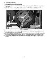
Located on the control board are the Control Board LED’s. See
Figure 7
.
2.
Verify that the “Power LED” is Green signifying the NPVD is on.
3.
The “System Pulse LED” will be dull red showing the control board is running.
4.
The “Camera On LED” is lit when the motion detection is selected and off when the auxiliary input is selected.
Figure 7: Control Board
Figure 7 Detail A: Switches
Camera
On LED
Control Board
Option Switches
Power
LED
System Pulse
LED
Options may be controlled via the four “Option Switches,” see
Figure 7
, see
Detail A
for their respective functions. It is
advised to verify operation first by using the On Screen PVD Menu to control these options. After verification of settings via
the PVD Menu the Control Board Option switches can be accessed.
7.2 Detail of Option Switches
1
2
3
4
Motion
Switcher
Ambient Light
Control
Synchronization
Mode
Light Sensor
Disable Motion Switcher
Control of Aux Video Amp
No Control of Aux Video Amp
Sync to Aux Video
Sync to Line
Enable Light Sensor
Disable Light Sensor
ON
OFF
ON
OFF
ON
OFF
on
on
on
on
1
2
3
4
Note:
is factory setup
Detail A
Note:
Option switches are only field - accessable in on-board camera models.


