Doc
No.
FM5640
issue
3
Page
22
15.
IP
‐
DECT
400
SINGLE
‐
CELL
SYSTEM
INSTALLATION
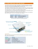
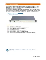
IP-DECT SERVER 400 (SINGLE-CELL) PROGRAMMING
The
IP
‐
DECT
Server
400
must
have
its
IP
address
set
to
192.168.0.3
and
its
Radio
Part
Number
set
to
3.
Refer
to
the
manufacturers
installation
guide
for
full
instructions
‐
see
section
6.
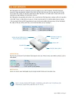
2 CHANNEL MULTI-CELL REPEATERS
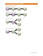
A
maximum
of
six
2
Channel
Multi
‐
Cell
Repeaters
can
be
used
with
the
IP
‐
DECT
Server
400
Single
‐
Cell.
Repeaters
require
a
power
connection
only;
they
communicate
with
the
Server
via
low
power
radio
signals
and
do
not
require
a
line
connection.
To
maintain
DECT
coverage
during
a
mains
failure
all
Repeaters
must
be
connected
to
a
battery
backed
12V
DC
PSU.
REPEATER POSITIONING
Before
installing
power
cables
to
Repeater
positions,
it
is
important
that
the
optimum
position
for
coverage
is
established.
Register
the
Repeater
onto
the
IP
‐
DECT
Server
400
then
with
the
Repeater
powered
from
a
battery
walk
away
in
the
direction
that
cover
is
to
be
extended.
When
the
red
LED
on
the
Repeater
starts
to
flash
it
is
out
of
range
and
must
be
moved
back
towards
the
Server
by
a
minimum
of
5
metres
before
selecting
its
final
location.
The
LED
should
be
steady
green.
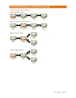
See
Repeater
Deployment
Rules
on
the
following
page.
REPEATER PROGRAMMING
Refer
to
the
manufacturers
installation
guide
for
full
instructions
–
see
section
6.
A
programming
kit
(P/No.
ZCS729)
is
required
to
program
Repeaters,
the
Service
Tool
software
can
be
downloaded
via
the
link
in
section
6
of
this
manual.
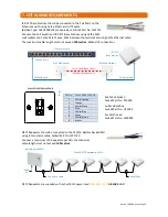
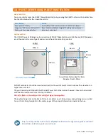
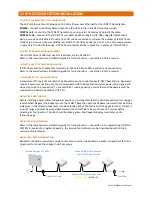
REPEATER POWER CONNECTION
Repeaters
should
be
connected
using
8
core
cables;
cores
can
be
doubled
‐
up
and/or
looped
back
to
form
a
ring
circuit
to
reduce
the
voltage
drop
if
necessary.
Typically,
the
maximum
distance
to
a
Repeater
should
not
exceed
100
metres.
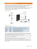
Maximum
6
x
2
Channel
Multi
‐
Cell
Repeaters
240V
AC
Battery
Backed
12V
DC
PSU
Repeater
Power
Lead
Colour
Code
YELLOW
=
12V
BLACK
=
0V
Use
8
Core
Cable
Max
100m

