background image

Waste disposal 

3.3 Waste disposal

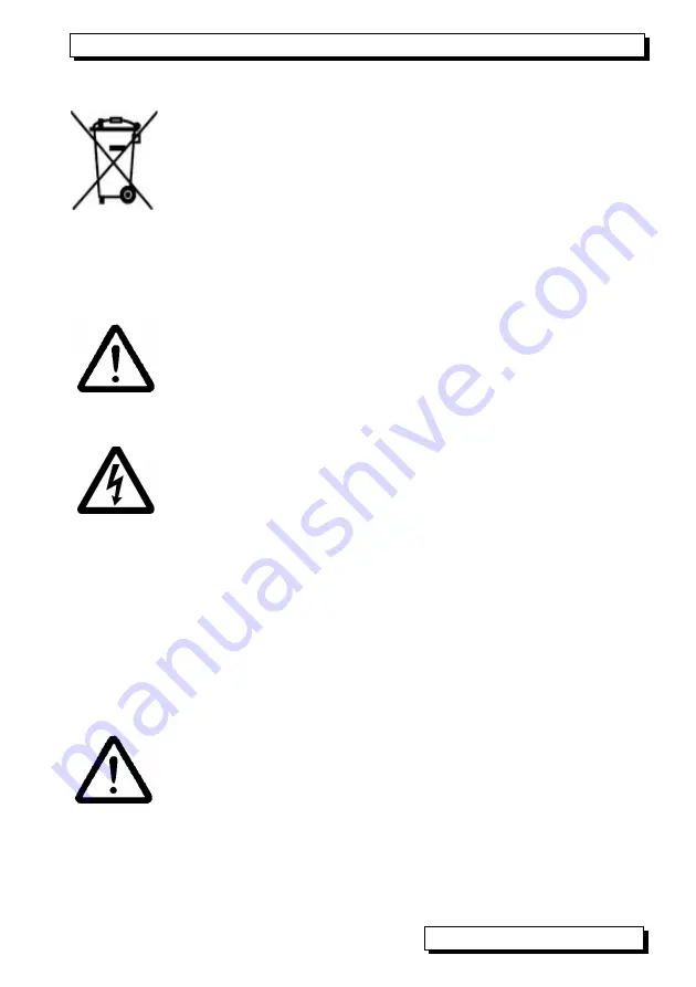
This   symbol   means   that   the   product   is   subject   to   European

Union regulations on segregated waste disposal.   This applies

both to the product itself and to any accessories   marked with

the same symbol.   Disposal of any such item as unsorted do-

mestic   waste   is   strictly  forbidden.  Batteries  and  rechargeable

battery packs are special waste and must not be discarded as

normal domestic waste. Please dispose of packaging materials,

plastics,   and   electronic   components   separately   and   in   the

proper manner.

4. SAFETY INSTRUCTIONS

CAUTION!

  This sign is intended to warn the user of a situation

that risks damaging the device. The user should carefully read

the operating instructions in order to avoid possible errors, dam-

age to equipment, and even the risk of personal injury. The de-

vice may only be opened by duly authorized and qualified service

technicians.

WARNING!

 This sign is intended to warn the user of a possibly

life-threatening situation with risk of fatal injury through high volt-

age. Before connecting any equipment to the power supply al-

ways ensure that the operating voltage is correct. Please note

that the device may be susceptible to damage by electrostatic

discharge or lightning. Do not run wires in the vicinity of high-volt-

age power cables!

4.1 Special notes on use

If the device is brought into the work-room from a cold environ-

ment there is a risk that condensation might form on the electron-

ics. You are advised therefore to wait until the device has ad-

justed to the ambient temperature before starting to use it.

4.2 Handling batteries / rechargeable batteries correctly

When   inserting   batteries   /   rechargeable   batteries   ensure   that

these are correctly polarized. If the device will probably not be

needed for a relatively long period of time or if the batteries are

empty remove the batteries; this will prevent battery acid leaking

onto the device and damaging it. Rechargeable batteries should

be recharged as and when necessary. You should never attempt

to  recharge   an  ordinary  (non-rechargeable)  battery;  it  may  ex-

plode ! Batteries / rechargeable batteries must never be short-cir-

cuited or thrown on the fire.

 ALMEMO

®

 KA7531

5  

Summary of Contents for Almemo KA 7531

Page 1: ...____________________________ Operating instruction English Simulator ALMEMO KA 7531 V1 4 03 12 2012 www ahlborn com...

Page 2: ...2V and RS422 ZA 5099 FSV 9V and USB ZA 1919 DKUV 4 LCD graphics display 7 rows for functions 1 row for softkeys F1 F2 Shown in brackets SET 5 Operating keys CONFIG Device configuration MENU Main menu...

Page 3: ...8 8 1 Function keys 8 8 2 Data entry 8 9 MENUS 9 9 1 Main menu 9 9 2 Submenus 9 9 2 1 Pt100 output 9 9 2 2 Voltage output thermocouples 10 9 2 3 Current output 10 9 2 4 Digital signal output 11 9 2 5...

Page 4: ...ree In the unlikely event that the device proves defective and you need to return it please wherever possible use the original packaging material for dispatch and enclose a clear and informative descr...

Page 5: ...al injury through high volt age Before connecting any equipment to the power supply al ways ensure that the operating voltage is correct Please note that the device may be susceptible to damage by ele...

Page 6: ...width or pulse pause duration A continuity check is also provided this measures the voltage drop and in the event of the result exceeding a settable threshold issues an acoustic signal The simulator c...

Page 7: ...the device itself will switch off To replace old batteries unscrew the battery compartment cover 6 on the rear of the device To save on battery use when in battery mode the electrically isolated curr...

Page 8: ...switch device OFF press and hold down ON To select a function press any of keys PROG oder Symbol lights up in the middle indicating function selection F f r Funktionswahl The function is highlighted i...

Page 9: ...directly by means of keys PROG see 8 2 The threshold for the continuity check can be programmed via port P4 The ports can be configured in detail via the appropriate sub menus The 5 Pt100 values can a...

Page 10: ...temperature of test item must either be disabled in the test item or im aged in the simulator To select the cold junction temperature press VK Enter the cold junction temperature in the function press...

Page 11: ...n there is a further sub menu this can be accessed by pressing the F key again To return to the 1st submenu press F 9 2 5 Continuity check The test cable connected at socket P4 provides a continuity c...

Page 12: ...atically modifica tion of the control variable can be automated In the function Time the waiting period per step can be entered To start step by step output press START To stop step by step output pre...

Page 13: ...or display illumination ON Duration 20 sec To switch illumination ON permanently Duration To switch back ON again without this function ON or Set the contrast 5 to 100 in the function Contrast 50 9 4...

Page 14: ...the appropriate keys but also with option I via the serial interface see Manual Chapter 6 For connecting to socket A1 2 various data cables are available see Manual 5 2 The best way of connecting to a...

Page 15: ...nalog output 10 V Controlled 01 DA1 COM 10 000 V 01 Analog output 60 mV Controlled 01 DA7 COM 60 000mV 01 Analog output TC type K Controlled 01 TC0 COM 1370 0 C VK 025 1 C 01 Analog output TC type N C...

Page 16: ...label and complies in full with the requirements of EU directives relating to low voltage and to electromag netic compatibility EMC 89 336 EWG The following standards have been applied in evaluating t...

Page 17: ...er supply 10 to 12 VDC Current consumption Standard approx 30 mA From battery 4 5 V With voltage current output approx 80mA 4x IOUT Illumination approx 40 mA extra Standard equipment Graphics display...

Page 18: ...cable 12 2 14 17 Device address 9 4 5 14 Device configuration 9 4 13 Digital signal output 9 2 4 11 Display and operating controls 8 8 duration for display illumination 9 4 2 13 Electromagnetic compa...

Page 19: ...ons 9 3 12 softkey 8 1 8 Special notes on use 4 1 5 Standard delivery 3 2 4 Standard equipment 12 1 17 start 9 3 2 12 start value 9 3 3 12 step percentage 9 3 1 12 Steps 9 3 1 12 stop 9 3 2 12 stop va...

Page 20: ...echnik GmbH Eichenfeldstra e 1 83607 Holzkirchen Germany internet http www ahlborn com e mail amr ahlborn com Even the greatest possible care cannot exclude the possibility of inaccuracies We reserve...

Reviews: