


01
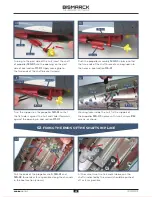
. FITTING THE TWO OUTER PROPELLERS
01
02
121-01
PM
2 x 4
PM
2 x 3
121-03
121-02
PM
2 x 4
B
A
A
115-01
PM
PM
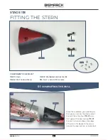
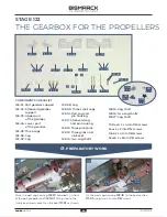
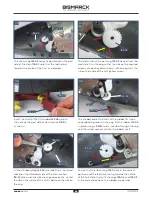
STAGE 121
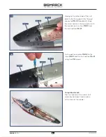
THE CENTRAL PROPELLER
COMPONENTS CHECKLIST
121-01:
Motor for the propellers
121-02:
Central propeller with
shaft, support and sleeve
121-03:
Cable label (D-2)
PM:
Four 2 x 4mm PM screws
PM:
Two 2 x 3mm PM screws
NOTE:
You will also need all the parts
supplied with stage 120. The 2 x 3mm
PM screws are not used in this stage,
so store them safely for later.
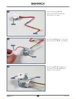
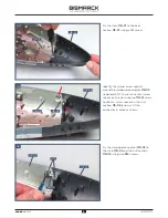
Fit the bracket marked L on the two pegs located on
the port side of the keel section
115-01
. Fix in place
with two 2 x 4mm
PM
screws, as shown.
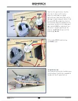
Place your model on your work surface so that you
can access the stern of the hull. Take the brackets
A
and
B
(marked L and R) from the frame
120-03
. You
will also need four 2 x 4mm
PM
screws.
15
15
AGORA
MODELS
PB
AGORA
MODELS


