


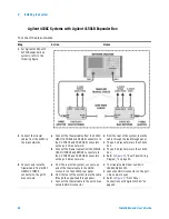


Installing the System
2
Installation and User’s Guide
85
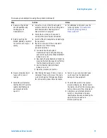
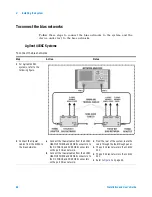
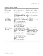
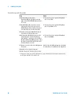
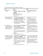
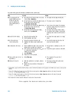
3 Connect the triaxial
cables from the
E5260A/70B SMUs to the
bias networks.
a Connect the triaxial cable from the
E5260A/70B medium power SMU to the
DC FORCE and DC SENSE connectors on
the port 1 bias network.
b Connect the triaxial cable from the
E5260A/70B high power SMU to the DC
FORCE and DC SENSE connectors on the
port 2 bias network.
•
The medium power SMU is the Agilent
E5281A.
•
The high power SMU is the Agilent
E5280A.
•
The port 1 bias network is the 11612V
K11.
•
The port 2 bias network is the 11612V
K21.
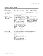
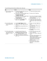
4 Connect and route the
ground cable from
E5260A/70B GNDU to the
port 2 bias network.
a From the front of the system, connect one
end of the ground triaxial cable to the
GNDU connector on the E5260A/70B front
panel.
b From the front of the system, route the
cable through the upper feedthrough panel.
c From the rear of the system, route the
ground triaxial cable through the port 2 hole
in the lower feedthrough panel.
d Connect the ground triaxial cable to the
port 2 bias network GNDU connector.
•
The ground triaxial cable model number
is 16493L Option 002.
•
Leave the GNDU connector on the port
1 bias network open.
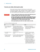
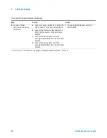
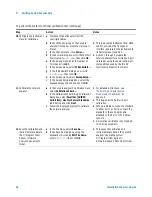
5 Connect the Agilent
E8364B test ports to the
bias networks.
a Connect one end of the port 1 test port
cable to the Agilent E8364B test port 1.
b Connect the other end of the test port 1 test
port cable to the 2.4 mm female-to-male
adapter.
c Connect the 2.4 mm female-to-male
adapter to the RF IN connector on the
11612V Option K11 bias network.
d Connect one end of the port 2 test port
cable to the Agilent E8364B test port 2.
e Connect the other end of the test port 2 test
port cable to the 2.4 mm male-to-male
adapter.
f
Connect the other end of the 2.4 mm
male-to-male adapter to the RF IN
connector of the 11612V K21 bias network.
•
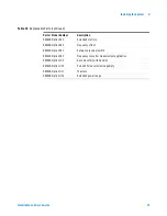
The test port cables model number is
85133F.
•
The 2.4 mm female-to-male adapter
model number is 11900C. Without this
adapter, the test port cable will not
properly mate with the bias network
RF IN connector.
•
The 2.4 mm male-to-male adapter
model number is 11900A.
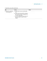
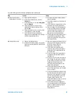
To connect the bias networks (continued)
Step
Action
Notes
Summary of Contents for 85225F
Page 1: ...Agilent Technologies Agilent 85225F PerformanceModelingSystem Installation and User s Guide ...
Page 90: ...90 Installation and User s Guide 2 Installing the System ...
Page 102: ...102 Installation and User s Guide 3 Verifying System Functionality ...
Page 110: ...110 Installation and User s Guide 4 Servicing the System ...
Page 118: ...118 Installation and User s Guide A Enhancing Measurement Accuracy ...
Page 128: ...128 Installation and User s Guide C RF Subsystem Functional Verification Test ...


