


80
Installation and User’s Guide
2
Installing the System
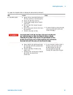
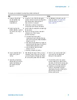
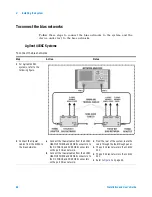
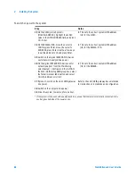
To connect the bias networks
Follow these steps to connect the bias networks to the system, and the
device under test to the bias networks.
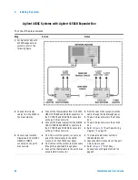
Agilent 4156C Systems
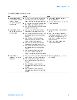
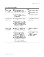
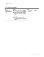
To connect the bias networks
Step
Action
Notes
1 For Agilent 4156C
systems, refer to the
following figure.
2 Connect the triaxial
cables from the 4156C to
the bias networks.
a Connect the triaxial cables from the 4156C
HRSMU1 FORCE and SENSE connectors to
the DC FORCE and DC SENSE connectors
on the port 1 bias network.
b Connect the triaxial cables from the 4156C
HRSMU2 FORCE and SENSE connectors to
the DC FORCE and DC SENSE connectors
on the port 2 bias network.
•
From the rear of the system, route the
cable through the feedthrough panel.
•
The port 1 bias network is the 11612V
K11.
•
The port 2 bias network is the 11612V
K21.
•
Refer to
Figure 5
on page 29.
Summary of Contents for 85225F
Page 1: ...Agilent Technologies Agilent 85225F PerformanceModelingSystem Installation and User s Guide ...
Page 90: ...90 Installation and User s Guide 2 Installing the System ...
Page 102: ...102 Installation and User s Guide 3 Verifying System Functionality ...
Page 110: ...110 Installation and User s Guide 4 Servicing the System ...
Page 118: ...118 Installation and User s Guide A Enhancing Measurement Accuracy ...
Page 128: ...128 Installation and User s Guide C RF Subsystem Functional Verification Test ...


