


100
Installation and User’s Guide
3
Verifying System Functionality
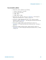
This completes the functional verification procedure.
15
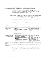
For systems with the
Agilent 4284A precision
LCR meter, open the
junction capacitance
model (juncap.mdl) in
IC-CAP.
a From the IC-CAP/Main window menu bar,
choose File > Examples... .
b In the Directories list of the File Open dialog
box, double-click on the directory
.../examples/model_files.
c In the Directories list of the File Open dialog
box, double-click on the directory
.../model_files/diode.
d In the Files list of the File Open dialog,
double-click on juncap.mdl.
•
This opens the File Open dialog box.
•
This opens a list of model files.
•
(Scroll the list, if needed.) This displays
a list of modeling files in the Files list of
the File Open dialog.
•
This opens the juncap model window.
•
The juncap model window contains tab
folders used to interact with the model
data.
16 Select the DUT/Setup.
a Select the DUTs-Setups tab.
b Click the area > cv setup.
•
This opens the capacitance vs. voltage
setup.
17 Set the LCR meter
instrument options.
a Select the Instrument Options tab.
b Highlight the Cable Length variable and
enter
2
.
•
This sets the cable length in the LCR
meter instrument options.
18 Calibrate the LCR meter.
a On the 16048D test leads, connect one tee
between the H
pot
and H
cur
connectors.
b Connect the other tee between the L
pot
and
L
cur
connectors. Select the
Measure/Simulate tab.
c Select Calibrate.
d Follow the IC-CAP prompts.
•
This performs a calibration on the LCR
meter.
•
The BNC tee part number is 1250-2405.
19 Measure the open circuit
capacitance.
a Select Measure.
•
This measures the open circuit
capacitance.
20 Observe the results
a After the calibration is complete, observe
the plot.
b Rescale the measured result (displayed in
red) cap.m.
•
The measured result should be less
than ±10E-15 farads.
* To familiarize yourself with the IC-CAP software, refer to the first three chapters of the Agilent IC-CAP 2004 User’s Guide, model number
85190D.
† To save this hardware configuration: on the IC-CAP main menu bar, choose File > Save As and enter a filename, for example
config1.hwd
(the file suffix must be
.hwd
).
‡ To save this hardware configuration: on the IC-CAP main menu bar, choose File > Save As and enter a filename, for example
config1.hwd
(the file suffix must be
.hwd
).
**S12 is identical to S21 because the attenuator is assumed to be symmetrical.
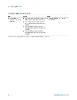
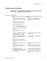
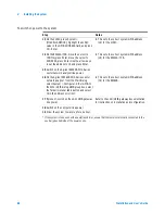
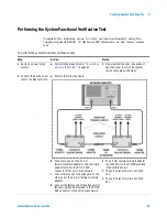
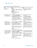
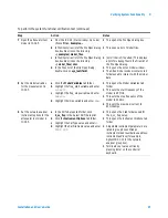
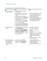
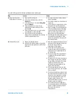
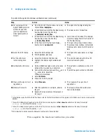
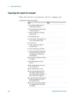
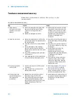
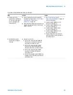
To perform the system functional verification test (continued)
Step
Action
Notes
Summary of Contents for 85225F
Page 1: ...Agilent Technologies Agilent 85225F PerformanceModelingSystem Installation and User s Guide ...
Page 90: ...90 Installation and User s Guide 2 Installing the System ...
Page 102: ...102 Installation and User s Guide 3 Verifying System Functionality ...
Page 110: ...110 Installation and User s Guide 4 Servicing the System ...
Page 118: ...118 Installation and User s Guide A Enhancing Measurement Accuracy ...
Page 128: ...128 Installation and User s Guide C RF Subsystem Functional Verification Test ...


