Terminator Chip
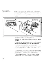
Removal Procedure In order to gain access to the Processor Board you must remove
the Low Voltage Power Supply. You do not need to disconnect the
AC or DC power connectors because you will only move the Power
Supply module to another spot. You will not remove it entirely from
the unit.
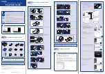
Figure 5-5. Low Voltage Power Supply Removal
Remove the Low Voltage Power Supply by performing the following
procedure.
• Remove the four flat-head screws and flat washers that secure
the Low Voltage Power Supply to the unit. Save all hardware.
• Remove the P8 Connector from the Processor Board.
» Slide the low voltage power supply partially out of the unit and
rest it on the CRT plate. You now have service access to the
Processor Board.
• Terminator Chips U1 and U2 are located next to the 50 pin SCSI
ribbon cable J1 on the Processor Board. Carefully remove both U1
and U2 using an IC extractor or a small flat tip screwdriver.
• Save both terminator chips in case you decide to place the
SlideWriter at the end of the device chain at some later date.
40


