19
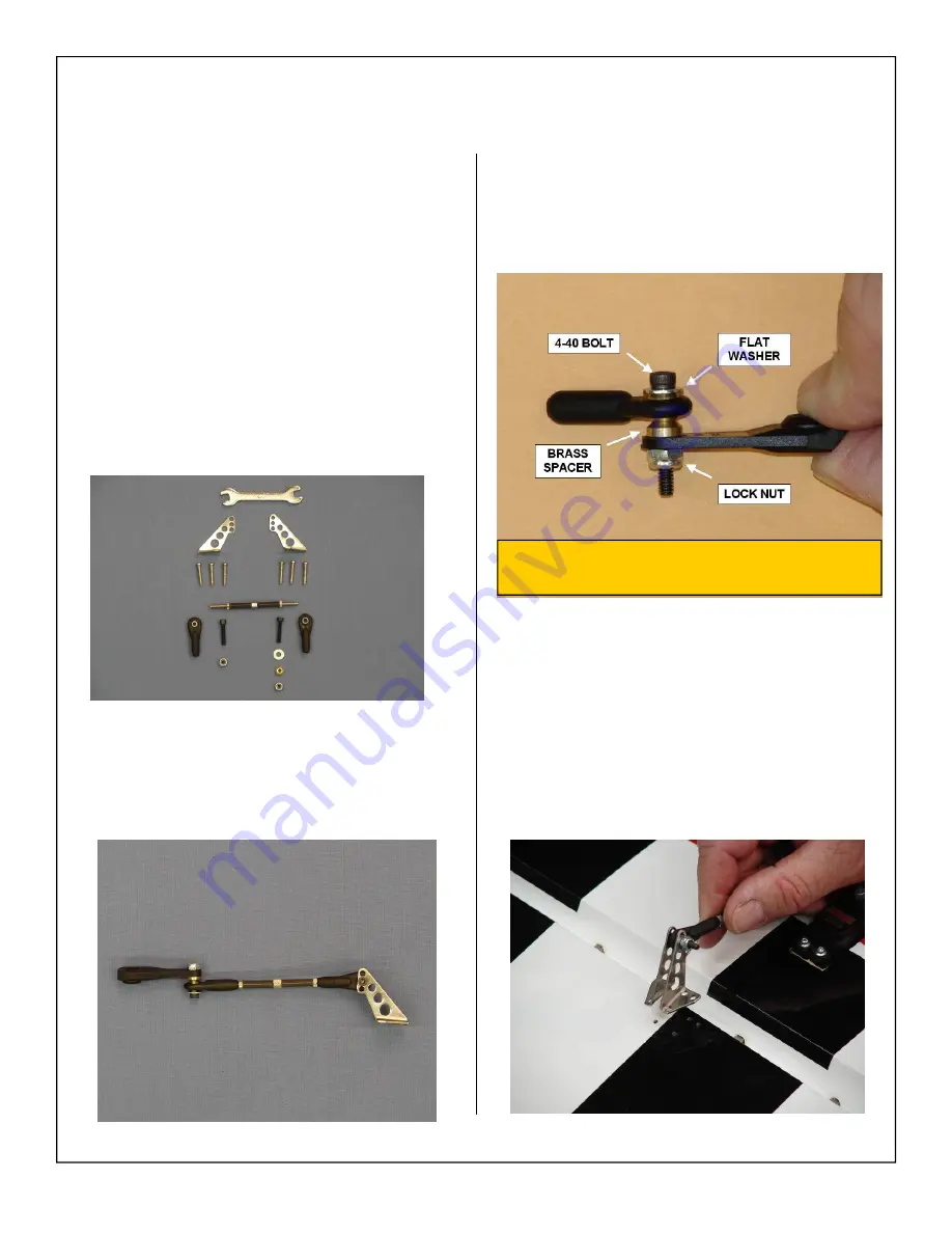
4. Align the control horns over the factory drilled
holes.
Note:
Control horns have been set at a slight
offset to allow for maximum torque at full
deflection.
2. Assemble the pushrod and control horn assem-
bly as shown. The ball link goes between the
left and right sides of the control horn sides and
is secured with a nylon lock nut.
1. Gather the following items for installing the ele-
vator linkage:
◊
1 - 2 1/2” pushrod
◊
2 - 4-40 ball link assemblies
◊
1 - Brass spacers
◊
1 - Flat washer
◊
1 - Left control horns
◊
1 - Right control horns
◊
6 - Wood screws for each wing panel
◊
1 - Adjustment wrench
Elevator Control Linkage Installation
3. Correct installation of ball link, flat washer and
brass spacer to servo arm shown below.
Note:
Flat washer prevents ball link from
coming off brass ball.


