background image

BL

Introduction

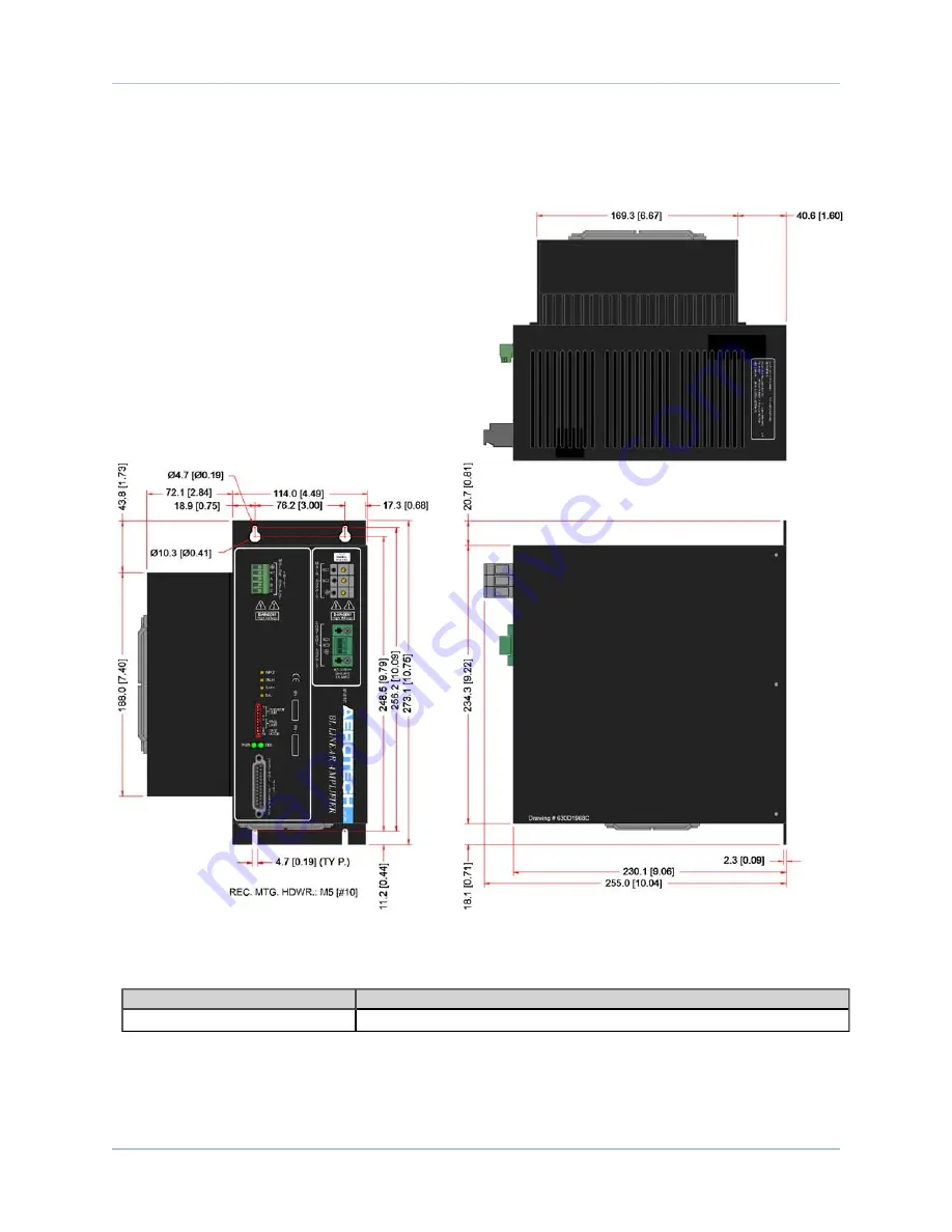
1.2. Mechanical Design

Each unit should be separated from other drives and surrounded by 50 mm (2") of free air space. A space of

100 mm (4") should be allowed along the front of the unit for cable connections.

Figure 1-3:

Dimensions

Table 1-3:

Physical Specifications

Model

Weight

BL

8.5 kg [18.8 lb]

4

Chapter 1

www.aerotech.com

Summary of Contents for BL 10-40

Page 1: ...BL Hardware Manual Revision 2 02 00 Dedicated to the Science of Motion Aerotech Inc 101 Zeta Drive Pittsburgh PA 15238 Phone 412 963 7470 Fax 412 963 7459 www aerotech com...

Page 2: ...1742 Fax 81 0 47 489 1743 Email service aerotechkk co jp China Phone 852 3793 3488 Email saleschina aerotech com Revision History 2 02 00 11 11 10 2 01 00 6 22 10 2 00 00 3 16 10 1 08 8 11 09 1 07 12...

Page 3: ...6 3 Input 18 2 6 4 Limit Inputs J101 19 2 6 5 Current Command Inputs J101 20 2 6 6 Tach Input J101 21 2 6 7 Shutdown Input J101 22 2 6 8 Fault Output J101 23 2 7 Motor and Feedback Phasing 24 Chapter...

Page 4: ...BL Table of Contents iv www aerotech com...

Page 5: ...ach Input 21 Figure 2 10 Shutdown Input 22 Figure 2 11 Fault Output 23 Figure 2 12 Motor Phasing Oscilloscope Example 25 Figure 2 13 Hall Phasing with Oscilloscope 26 Figure 2 14 Brushless Motor Phasi...

Page 6: ...BL List Of Figures vi www aerotech com...

Page 7: ...Mode Current BL Configuration 34 Table 3 3 Dual Phase Mode BL Configuration 35 Table 3 4 Differential Dual Phase Mode BL Configuration 36 Table 3 5 Single Brush Motor Mode BL Configuration 37 Table 3...

Page 8: ...BL List of Tables viii www aerotech com...

Page 9: ...ective s 2006 95 EC Low Voltage Directive 2004 108 EC Electromagnetic Compatibility Directive and is in conformity with the applicable requirements of the following documents when installed and used i...

Page 10: ...x www aerotech com BL Declaration of Conformity...

Page 11: ...n the control stage and the power stage for all models of the BL This is accomplished with a trans former isolated control voltage power supply and opto isolation of the drive signals current command...

Page 12: ...ushless motor electronic Tachometer 0 commutation offset Aerotech standard VM2 Brushless motor electronic Tachometer 30 commutation offset VM3 Brush motor analog Tachometer VM4 Brush motor electronic...

Page 13: ...5 240 VAC Input Frequency 50 60 Hz Inrush Current 16 A Input Current 25 A max Output Voltage 1 36V 20A 38V 20A 78V 10A Peak Output Current 20 10 10 Continuous Output Current 10 5 5 Power Amplifier Ban...

Page 14: ...from other drives and surrounded by 50 mm 2 of free air space A space of 100 mm 4 should be allowed along the front of the unit for cable connections Figure 1 3 Dimensions Table 1 3 Physical Specific...

Page 15: ...ing 5 to 40 C 41 to 104 F Storage 20 to 70 C 4 to 158 F Humidity Maximum relative humidity is 80 for temperatures up to 31 C Decreas ing linearly to 50 relative humidity at 40 C Non condensing Altitud...

Page 16: ...BL Introduction 6 Chapter 1 www aerotech com...

Page 17: ...tation offset Consult the motor manufacturer for details The BL amplifier must be installed inside an enclosure with construction compliant for use with unlimited cir cuits The BL amplifier can be lif...

Page 18: ...injury during operation due to moving parts connected to the BL Residual voltages greater than 60V can be present inside and at the terminals of the BL amplifier for longer than 5 seconds after power...

Page 19: ...n external fuse or circuit breaker 3 A time delay The figure below shows the required connections to the control power input N OTE This product requires two power supply connections The Motor Supply a...

Page 20: ...ration External fuses or a circuit breaker 10 A maximum time delay type are required for the AC1 and AC2 inputs for branch protection The protective device should be located near the drive Figure 2 2...

Page 21: ...Configurations for information on connecting each of the supported motor types Table 2 4 Motor Output Connection Pin Description Recommended Wire Size A Phase A Motor Lead 2 0 mm2 14 AWG B Phase B Mo...

Page 22: ...osing this position allows the BAL pot to manually control motor velocity or torque without the need of an input signal depending upon the setting of switch 10 Mode 10 Velocity Current mode closing th...

Page 23: ...itch Equation Example Setting Continuous Current Limits BL20 To set the continuous current limit to 5 5A 5 5A Continuous RMS x 1 414 7 8A continuous peak 7 8A continuous peak 20A max peak x 100 39 Ope...

Page 24: ...INPUT Increase Decrease This pot adjusts the DC gain of the input com mand present at J101 Pins 8 21 TACH Increase Decrease This pot adjusts the DC gain of the tach or encoder derived velocity feedbac...

Page 25: ...OWN Shut off power stage and remove all power to the motor Input1 11 ILMT CW directional current limit input Input1 12 ICMDC Current Command C Input 13 14 GROUND Signal common of an encoder N A 15 TAC...

Page 26: ...1 Encoder Inputs J101 The Encoder input signals provide encoder position information to the amplifier The encoder inputs can also be used to derive an electronic tachometer signal Figure 2 4 Encoder...

Page 27: ...signals provide motor rotor position information to the amplifier Hall effect input signals are recommended for AC brushless motor commutation but not absolutely required The Hall effect inputs accep...

Page 28: ...city mode For single ended oper ation connect command to this input and ground Pin 21 of J101 A positive voltage on J101 21 causes CW motor rotation torque or velocity mode For single ended com mand o...

Page 29: ...Installation and Configuration BL 2 6 4 Limit Inputs J101 When pulled to its active state motion is inhibited jumper selectable Figure 2 7 Limit Inputs www aerotech com Chapter 2 19...

Page 30: ...rential input pre amplifier and self commutation circuits J101 12 allows control of phase C current when jumper JP8 is set to 2 3 Normally phase C current is derived internally from phase A and B curr...

Page 31: ...guration to provide negative feedback to the amplifier This allows the amplifier to close the servo loop and control the stability of the loop If an encoder is used for velocity feedback this pin serv...

Page 32: ...figuration 2 6 7 Shutdown Input J101 Jumper selectable active high or active low input It is used to shut off power stage and therefore remove all power to the motor Figure 2 10 Shutdown Input 22 Chap...

Page 33: ...Jumper selectable active high or active low open collector output It is used to indicate the status of the power stage amplifier enabled or faulted The output device Q22 can sink up to 160 mA of curre...

Page 34: ...e voltages motor output con nections A B and C with respect to a real or pseudo neutral connection are shown in Figure 2 12 The volt ages generated are made under the conditions of a positive signal p...

Page 35: ...oscilloscope to TP1 Connect channel 2 to TP2 and move the motor in the positive direction CW by hand Note the peak of the sine wave signal of channel 1 in comparison to the peak of the sine wave sign...

Page 36: ...of the motor leads connect channel 2 of the oscilloscope to TP5 TP6 and then TP7 while advancing the motor in the positive direction after each connection Note which of the three Hall signals has the...

Page 37: ...tech system Connect motor lead A to motor connector A motor lead B to motor con nector B and motor lead C to motor connector C Connect Hall lead A to Pin 4 of the feedback connector Hall lead B should...

Page 38: ...BL Installation and Configuration 28 Chapter 2 www aerotech com...

Page 39: ...tions BL Chapter 3 Wiring Configurations BL drives can be wired into a system in one of two modes brush or brushless For a list of motor and feed back cables refer to Section 3 8 Cables www aerotech c...

Page 40: ...drawback This drawback is phase winding imbalances that can cause torque ripple and make it difficult to compensate since the servo amplifier only controls two of the three phase currents The BL Seri...

Page 41: ...to the TACH pin or from an incremental encoder that is connected to the sine and cosine pins refer to Figure 3 2 From this signal the amplifier adjusts the velocity of the motor accordingly depending...

Page 42: ...on is between 1 000 and 1 500 per revolution 2 For more information about the DIP Switch refer to Section 2 4 DIP Switch 3 For more information about the Potentiometer refer to Section 2 5 Potentiomet...

Page 43: ...tor is proportional to the current command input The advan tage to this configuration is that the sine and cosine signals to the amplifier and a tachometer are not required This configuration will dri...

Page 44: ...IN 2 3 OUT6 0 Commutation JP4 JP10 JP12 JP10 1 2 in 2 3 out Full Step AC Commutation JP12 1 2 in 2 3 out Full Step AC Commutation JP4 1 2 out 2 3 in 30 Commutation Offset JP82 1 2 IN 2 3 OUT6 Standard...

Page 45: ...ion is that it provides the smoothest possible motion This mode is used with a brushless motor only Figure 3 4 Dual Phase Command Configuration Table 3 3 Dual Phase Mode BL Configuration Jumpers 1 Set...

Page 46: ...s that it provides the smoothest possible motion This mode is used with a brushless motor only Figure 3 5 Differential Dual Phase Command Configuration Table 3 4 Differential Dual Phase Mode BL Config...

Page 47: ...safely with BL Connecting the motor to the amplifier at the phase A and phase C connections allows the motor to see the entire bus Meaning if a BL10 40 is the amplifier then the brush motor will have...

Page 48: ...each motor with 40 volts and a BL10 80 drives each motor with 80 volts Figure 3 7 Multiple Brush Motor Configuration Table 3 6 Multiple Brush Torque Command Mode BL Configuration Jumpers 1 Setting Des...

Page 49: ...9364 C21031 BLM 264A C19360 C19851 ABL9000 BLM 142A C21151 BLMH262A C21151 BLM 325A C21151 AHL9000 C19360 C19851 ALS130 25du C18982 C18983 C18984 4du 25du C19363 C19364 C21031 ALS130H 25du C18982 C189...

Page 50: ...101smb2 C20251 BMS60 C19363 C19364 C21031 ATS3600 1050msof BADC MSOHF 101smb2 C20251 BMS60 C19363 C19364 C21031 ATS5000 Standard C15805 C21663 ATS5000WB Wide Body C15805 C21663 ATS6200 310smb3 BM250 C...

Page 51: ...19364 C19851 Rotary C19360 C19851 LaserTurn 5 ASR Linear C19360 C19851 ASR Rotary C19360 C19851 ACS Linear C19363 C19364 C19851 ACS Rotary C19363 C19364 C19851 VascuLathe ASR Linear C19360 C19851 ASR...

Page 52: ...A1000 C19363 C19364 C19851 ALAR C19363 C19364 C19851 AMG A C19363 C19364 C19851 B C19360 C19851 ANT20RA C18982 C18983 C18984 ANT 4V 20RA C18982 C18983 C18984 AOM130 50smb2 C20251 BMS60 w o limits C193...

Page 53: ...000 C19360 C19851 ASR1100 C19360 C19851 ASR1200 C19360 C19851 ASR2000 C19363 C19364 C19851 AVL112 C19363 C19364 C19851 AVL125 C18982 C18983 C18984 AVL1000 C19363 C19364 C19851 AVS10x 50smb2 C20251 BMS...

Page 54: ...BL Wiring Configurations 44 Chapter 3 www aerotech com...

Page 55: ...y in velocity mode configuration Encoder sine and cosine signals or tach signals are improperly con nected Swap connections to change polarity of feedback Motor runs erratic in velocity mode using enc...

Page 56: ...ration capability of operating modes Table 4 3 lists the jumpers and the default configurations for the amplifiers Figure 4 1 highlights where the jumpers are located on the board Figure 4 1 BL Contro...

Page 57: ...erential Dual Phase Mode JP10 1 2 in 2 3 out Full Step AC Commutation 1 2 OUT 2 3 IN Half Step AC Commutation JP11 1 2 IN 2 3 OUT External Commutation 1 2 out 2 3 in Amplifier Commutation JP12 1 2 in...

Page 58: ...ntrol Board Test Points Test Point Description TP1 TP2 TP3 TP4 Common TP5 12V TP6 12V TP7 5V TP8 Analog Hall A TP9 Analog Hall B TP10 Current Command B TP11 Current Command A TP12 Current Command C 48...

Page 59: ...Table 4 5 BL Fuse Replacement Part Numbers Fuse Drive Size Aerotech P N Manufacturer s P N F1 F2 10 40 5A S B EIF01023 LittelFuse 215005 P 20 40 10A S B EIF01020 LittelFuse 215010 P 10 80 5A S B EIF0...

Page 60: ...ductive material must not be permitted to enter the BL W A R N I N G Disconnect power to avoid shock hazard Visually inspect all cables and connections Tighten or re secure any loose connections Repla...

Page 61: ...hether in warranty or out of warranty without first obtaining approval from Aerotech No credit will be given nor repairs made for products returned withoutsuch approval Any returned product s must be...

Page 62: ...rmal work periods then special service rates apply If during the on site repair it is determined the problem is not warranty related then the terms and conditions stated in the following On Site Non W...

Page 63: ...on History BL Appendix B Current Changes Table B 1 Revision 2 02 00 Manual Changes Section Description Chapter 2 Added supported wire gauges for quick connect terminal blocks www aerotech com Appendix...

Page 64: ...has been renamed Control Supply and AL1 and AL2 have been renamed AC1 and AC2 Figure 2 8 Figure updated 2 00 00 All Full Revision Section 4 1 Control Board Assembly Power board removed Control board...

Page 65: ...cations 3 Current Command Inputs J101 20 D Declaration of Conformity ix Differential Dual Phase Command Configuration 36 dimensions 4 DIP Switch 12 Dual Phase Command Configuration 35 E Electrical Spe...

Page 66: ...ower Amplifier Bandwidth specifications 3 Power Connections 9 Preventative Maintenance 50 Protective Features 3 R relative phasing order 25 S Safety Procedures and Warnings 8 Shutdown Input J101 22 Si...

Page 67: ...NO Adequate to the subject Well organized Clearly presented Well illustrated How do you use this document in your job Does it meet your needs What improvements if any would you like to see Please be s...

Page 68: ......

Reviews: