41
In case of not entering anything in the field „high level“ it will be ignored and just the „low level“ will be
considered as a threshold. In case of exceeding the “low level” the corresponding warning channel will
be set to logical-1. Will the “low level” be fallen short again than the warning channel will be set back to
logical-0.
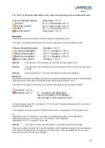
The thresholds inserted in the fields “low level“ and “high level“ will be interpreted from the met[LOG]
as a twisted full circle clockwise (similar to a wind direction sensor). This means that also such entries
are permitted where the value for the “low level” is higher than the value of the “high level”.
Example:
Low-Pegel = 30° High-Pegel = 60°
0°
360°
30°
60°
Warnsektor
Low-Pegel = 60° High-Pegel= 30°
0°
360°
30°
60°
Warnsektor
Alternatively, the in the example portrayed inverting can also be realized via the switch “inverted logic”.
With the switch “hysteresis function” the hysteresis function can be activated instead of the window
function with the “low level” and the “high level”.
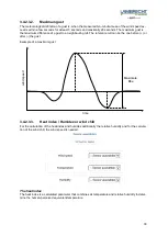
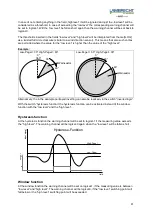
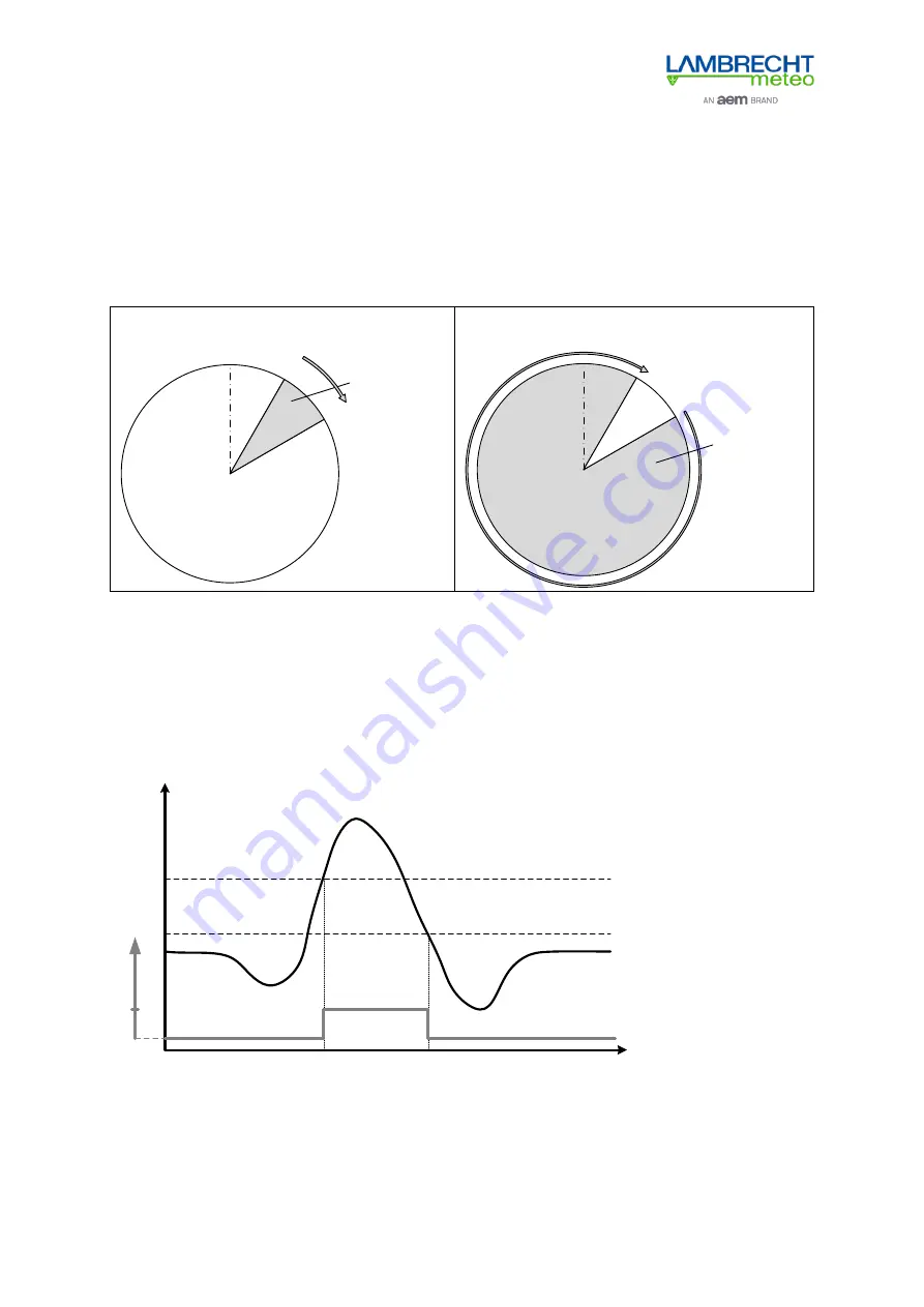
Hysteresis function
At the hysteresis function the warning channel will be set to logical-1 if the measuring value exceeds
the “high level”. The warning channel will be logical-0 again when the “low level” will be fallen short .
Input signal
time
Hysterese-Funktion
output
Low-Pegel
High-Pegel
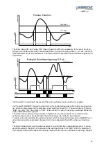
Window function
At the window function the warning channel will be set on logical-1, if the measuring value is between
“low level” and “high level”. The warning channel will be logical-0, if the “low level” switching point will
fall below or the “high level” switching point will be exceeded.

