IPC-622 User Manual
14
3.1
The Front Panel
The front panel features one Power On/Off switch, one Alarm Reset button, four Sys-
tem Reset buttons, and four USB ports. Nine LED indicators are located on the lock-
able front door; the individual functions of each are explained below.
3.1.1
Switch and Buttons
Power On/Off switch:
Press this button to turn the system power on or off.
System Reset button:
Press this button to reboot an individual system (up to four
systems).
Alarm Reset button:
When a system fault occurs (e.g., fan failure or the chassis
temperature is too high), an audible alarm is emitted. Pressing this button will termi-
nate the audible alarm.
3.1.2
LED Indicators for System Status
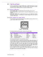
The LED panel on the front door features several indicators that are divided into two
groups - System Status and Power Status.
Figure 3.1 LED indicators
The following table describes the LED indicators for System Status.
When the system powers is on, the PWR LED is Green.
If the PWR LED is RED, this indicates a redundant power supply module failure. To
stop the audible alarm, press the Alarm Reset button. Examine the redundant power
supply module immediately and replace the failed module with a functioning module.
If the TEMP LED is RED, the inside of the chassis has overheated and an audible
alarm will be emitted. To stop the audible alarm, press the Alarm Reset button.
Inspect the fan filter and the rear section of the chassis immediately. Check that the
airflow inside the chassis is not blocked by dust or other particles.
When the FAN LED is RED, this indicates a failed cooling fan. An audible alarm will
also be emitted. To stop the audible alarm, press the Alarm Reset button and replace
the failed fan with a functioning fan immediately.
Table 3.1: LED Indicators for System Status
LED
Description
Green
Red
PWR
System power
Normal
Abnormal
HDD
Hard disk drive activity
Data access
No light
TEMP
Temperature in the chassis
Normal
Abnormal
FAN
Cooling fan status
Normal
Abnormal
Summary of Contents for IPC-622 Series
Page 1: ...User Manual IPC 622 Series 6U Multi Segment Rackmount Industrial Computer Chassis...
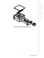
Page 27: ...19 IPC 622 User Manual Chapter 3 Operation Figure 3 8 Replacing the redundant power supply...
Page 28: ...IPC 622 User Manual 20...
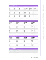
Page 36: ...IPC 622 User Manual 28 Table 4 22 PWR1 Pin 1 V12 Pin 4 GND Pin 2 GND Pin 5 V5...
Page 37: ...Appendix A A Exploded Diagram...
Page 39: ...Appendix B B Backplane Options...
Page 41: ...33 IPC 622 User Manual Appendix B Backplane Options...

