background image

IPC-622 User Manual

2

1.1

Introduction

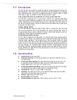
The IPC-622 is a 6U, rackmount industrial computer chassis designed for multi-sys-
tem applications. The device supports a backplane with up to 20 slots for a quad-seg-
ment industrial system, and can be configured to support a 400W, 500W, or 700W
PS/2 power supply, or a 500W or 750W redundant power supply. 

Unique alarm detection and notification to reduce system down time

The IPC-622 is equipped with a unique alarm module. This module automatically
detects the system operating conditions, such as the power status, HDD, fan, and
system temperature. The front LED indicators show the system and power status. In
the event of a system failure, the alarm module emits an audible beep to warn users
to take the necessary action.

Flexible storage options

The IPC-622 features numerous data storage options, including two drive housings
that can accommodate four front-accessible 5.25" devices (optical disk drives or
removable disk drives), and two internal 3.5" HDD. The IPC-622 chassis can be inte-
grated with a wide range of computing peripherals.

Outstanding mechanical designs 

The IPC-622 is designed for multi-system use. With abundant power supply options,
a superior airflow design, and support up to four high-speed cooling fans, this device
delivers reliable operation. The shockproof drive bay and rubber pads with rubber
cushions protect the system from harsh industrial environments and unexpected
shock. The front door with user-friendly rotary lock prevents unauthorized access to
the data storage. The redundant power supply module is hot-swappable and rear
accessible. All these easily maintained modules reduce the system’s Mean Time to
Repair (MTTR) and make IPC-622 the best solution in terms of price, performance,
and total cost of ownership.

1.2

Specifications                        

Construction

: Heavy duty steel

Disk drive capacity

: Four front accessible 5.25" disk drives and two internal 

3.5" disk drives 

Front panel LED indicators

: Bi-color LEDs (green/red) for Power, Fan, and 

Temperature status; single-color LEDs (green) for HDD activity and Single 
Power Status (+5 V, -5 V, +12 V, -12 V, and +3.3 V)

Front panel switch and buttons

: Power switch, Alarm Reset button, and up to 

four System Reset buttons located behind a lockable front door.

Cooling fans

: Four 9 x 9 cm (53 CFM) cooling fans 

Air filters

: Two filters (142 x 97 mm) located behind the front door. One filter 

(380 x 92 mm) behind the upper front cover.

Chassis color

: Beige (Pantone 414U) 

Gross weight

: 30 kg (66 lbs) 

Dimensions (W x H x D)

: 482 x 266 x 466.5 mm (19" x 10.5" x 18.4") 

Summary of Contents for IPC-622 Series

Page 1: ...User Manual IPC 622 Series 6U Multi Segment Rackmount Industrial Computer Chassis...

Page 2: ...proper installation Advantech assumes no liability under the terms of this warranty as a consequence of such events Because of Advantech s high quality control standards and rigorous testing most cust...

Page 3: ...been tested and found to comply with the limits for a Class A dig ital device pursuant to part 15 of the FCC regulations These limits are designed to provide reasonable protection against harmful inte...

Page 4: ...roblem The exact wording of any error messages Warnings Cautions and Notes Document Feedback To facilitate the ongoing improvement of this manual we welcome all comments and constructive criticism Ple...

Page 5: ...ot pour liquid into the openings This may cause fire or electrical shock 13 Never open the equipment For safety reasons the equipment should only be opened by qualified service personnel 14 If one of...

Page 6: ...e To avoid electrical shock always disconnect the power from the PC chassis before working on it Do not touch any components on the CPU card or other cards while the PC is turned on Disconnect the pow...

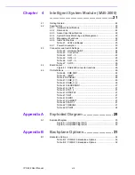
Page 7: ...using removal 11 Figure 2 6 Disk drive installation 11 2 5 Ear and Handle Attachment 12 Chapter 3 Operation 13 3 1 The Front Panel 14 3 1 1 Switch and Buttons 14 3 1 2 LED Indicators for System Status...

Page 8: ...25 Table 4 6 SW7 9 25 Table 4 7 SW10 25 4 4 Board Layout 26 Figure 4 1 SAB 2000 connector locations 26 4 5 Pin Definitions 26 Table 4 8 SMB_MB1 26 Table 4 9 IPMB1 26 Table 4 10 PSBUS1 26 Table 4 11 SM...

Page 9: ...Chapter 1 1 General Information This chapter provides general information about the IPC 622 Introduction Specifications Power Supply Options Environmental Specifications Dimension Diagram...

Page 10: ...t power supply options a superior airflow design and support up to four high speed cooling fans this device delivers reliable operation The shockproof drive bay and rubber pads with rubber cushions pr...

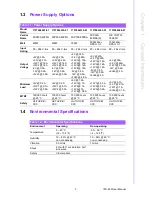
Page 11: ...V1 16A 12V2 16A 12V3 16A 12V4 16A 5V 0 3A 12V 0 5A 5Vsb 4 0A 5V 20A 3 3V 20A 12V1 16A 12V2 16A 12V3 16A 5V 0 3A 12V 0 5A 5Vsb 3A 5V 30A 3 3V 24A 12V1 60 9A 12V 0 5A 5Vsb 4A Minimum Load 5V 0 2A 12V1 0...

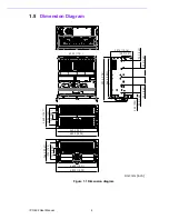
Page 12: ...Dimension diagram Unit mm inch 465 0 18 31 482 0 18 98 76 2 3 00 190 5 7 50 266 0 10 47 432 0 17 01 58 0 2 28 92 0 3 62 92 0 3 62 92 0 3 62 92 0 3 62 128 9 5 07 257 6 10 14 466 5 18 37 503 3 19 81 46...

Page 13: ...Chapter 2 2 System Setup This chapter explains the installa tion process Backplane Installation CPU Card Add on Card Instal lation Disk Drive Installation Ear and Handle Attachment...

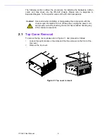
Page 14: ...moval To remove the top cover please refer to Figure 2 1 and proceed as follows 1 Loosen the eight screws on the sides and the three screws on the front of the top cover 2 Remove the top cover Figure...

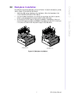
Page 15: ...e the backplane in the correct location and fasten to the chassis 2 For the PICMG1 0 backplane connect the orange white wire from connector HCN1 on the backplane to connector ATXF1 on the CPU card 3 C...

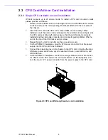
Page 16: ...the card bracket is correctly installed and the card edge is inserted into the plastic guiding fillister Affix the card to the top of the I O bracket using a screw 3 Repeat Steps 1 and 2 to install m...

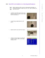
Page 17: ...nd changing the system from ATX to AT mode by following the instructions below 1 Locate the green black lines from the redun dant power supply and retrieve the AT switch from the accessory box 2 Conne...

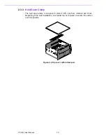
Page 18: ...old Down Clamp The hold down clamp is designed to protect CPU card from vibration and shock Regarding PCIe card installation one rubber foot is required to secure the add on card into position Figure...

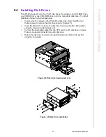
Page 19: ...isk drive shield Hold the two thumb screws to remove the disk drive housing Figure 2 5 2 Insert the disk drive in place in the disk drive housing and affix it into position using the screws provided F...

Page 20: ...User Manual 12 2 5 Ear and Handle Attachment A pair of ears and a pair of handles are provided in the accessory box Fasten them to the front right and front left edges of the chassis with the screws p...

Page 21: ...Chapter 3 3 Operation This chapter provides the system operation information The Front Panel Cooling Fan Replacement Filter Cleaning Power Supply Replacement...

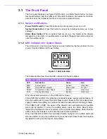
Page 22: ...ors for System Status When the system powers is on the PWR LED is Green If the PWR LED is RED this indicates a redundant power supply module failure To stop the audible alarm press the Alarm Reset but...

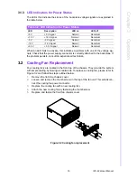
Page 23: ...em with ample cooling by blowing air rearwards To replace a cooling fan please refer to Figure 3 2 and follow the steps outlined below 1 Remove the front top chassis cover 2 Loosen and remove the thum...

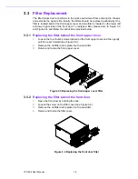
Page 24: ...uctions provided below 3 3 1 Replacing the filter behind the front upper cover 1 Loosen the four thumb screws located on the front upper cover and then gently pull the cover forward see Figure 3 3 2 R...

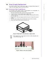
Page 25: ...the front panel to stop the alarm 2 Unplug the power cord on the failed power supply module 3 Loosen the screws on the module Grab the handle and gently pull the module out see Figure 3 5 4 Ensure th...

Page 26: ...he 8 screws on the top and sides of the rear lower plate 5 Remove the four screws that fasten the power supply module to the rear plate Remove the rear lower plate and retrieve the power supply module...

Page 27: ...19 IPC 622 User Manual Chapter 3 Operation Figure 3 8 Replacing the redundant power supply...

Page 28: ...IPC 622 User Manual 20...

Page 29: ...elligent System Module SAB 2000 This chapter introduces the alarm board and thermal sensor specifi cations Getting Started Specifications Connectors and Switch Settings SAB 2000 Board Layout SAB 2000...

Page 30: ...bus interface for monitoring the system and main board status Up to four external temperature sensors Seven fan tachometer inputs One external IPMI module connector One built in buzzer for system heal...

Page 31: ...mmand to search Blinking Warn Keep beep HDD Normal Normal Data transferring Blinking FAN Normal 500 rpm Normal CPU FAN fail 500 rpm Warn Keep beep System fan fail 500 rpm Blinking Warn Keep beep TEMP...

Page 32: ..._3V_1 SMBus Device Connector SMB_3V_2 SMBus Device Connector BZ1 External Buzzer Connector HDD1 HDD LED connector PWR1 PSU Power Connector SMB_MB1 Main Board SMBus Connector RDUPG1 Power Good Input Co...

Page 33: ...ct 2 2 ON ON OFF Connect 3 1 ON ON ON Connect 3 2 Table 4 5 SW4 6 SW1 Pin4 SW1 Pin5 SW1 Pin6 SYS FAN Qty OFF OFF OFF Disable OFF OFF ON 1 FAN1 OFF ON OFF 2 FAN1 2 OFF ON ON 3 FAN1 3 ON OFF OFF 4 FAN1...

Page 34: ...Pin 1 I2C_SCLK Pin 2 I2C_SDAT Table 4 9 IPMB1 Pin 1 NC Pin 3 S_SDAT_R Pin 2 S_SCLK_R Pin 4 GND Table 4 10 PSBUS1 Pin 1 V_PMBUS Pin 4 I2C_SDAT Pin 2 GND Pin 5 I2C_SCLK Pin 3 NC Table 4 11 SMB_3V_1 Pin...

Page 35: ...15 V5_SB_R Pin 8 P F_LED Table 4 14 VOLT1 Pin 1 V5_SB Pin 5 V5 Pin 2 GND Pin 6 V3 3 Pin 3 GND Pin 7 V12 Pin 4 V5 Pin 8 V12 Table 4 15 TR1 4 Pin 1 TEMP_SEN1 4 Pin 2 GND Table 4 16 RDUPG1 Pin 1 GND Pin...

Page 36: ...IPC 622 User Manual 28 Table 4 22 PWR1 Pin 1 V12 Pin 4 GND Pin 2 GND Pin 5 V5...

Page 37: ...Appendix A A Exploded Diagram...

Page 38: ...IPC 622 User Manual 30 A 1 Exploded Diagram Figure A 1 Exploded diagram 1 Figure A 2 Exploded diagram 2...

Page 39: ...Appendix B B Backplane Options...

Page 40: ...PCA 6120P12 Single 1 1 11 7 PCA 6120P4 Single 2 4 14 PCA 6119P17 Single 1 1 16 PCA 6119P7 Single 2 7 10 PCA 6120DP4 Dual 4 2 6 7 PCA 6120Q Quad 20 PCA 6116QP2 Quad 7 8 1 Table B 2 PCIMG 1 3 Backplane...

Page 41: ...33 IPC 622 User Manual Appendix B Backplane Options...

Page 42: ...subject to change without notice No part of this publication may be reproduced in any form or by any means including electronically by photocopying recording or otherwise without the prior written per...

Reviews: