IPC-622 User Manual
6
The following section outlines the procedures for installing the backplane, add-on
cards, and disk drives into the IPC-622 chassis. Please refer to Appendix A,
Exploded Diagram, for the specific names of the IPC-622 components.
2.1
Top Cover Removal
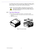
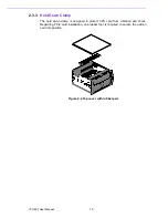
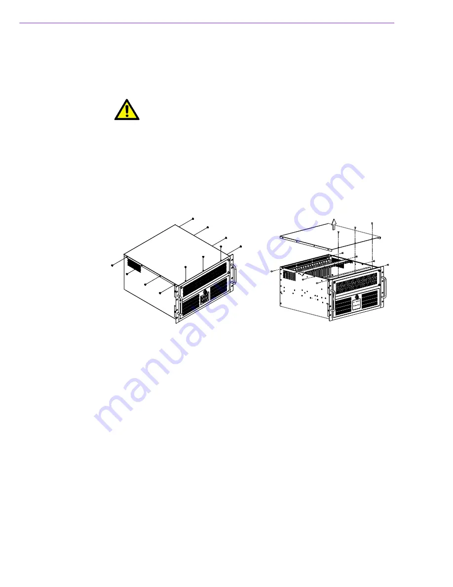
To remove the top cover, please refer to Figure 2.1 and proceed as follows:
1.
Loosen the eight screws on the sides and the three screws on the front of the
top cover.
2.
Remove the top cover.
Figure 2.1 Top cover removal
Caution!
Use caution when installing or manipulating the components with the
chassis open. Remember to turn off the power, unplug the power cord,
and ground yourself by touching the metal chassis before handling any
of the internal components.
Summary of Contents for IPC-622 Series
Page 1: ...User Manual IPC 622 Series 6U Multi Segment Rackmount Industrial Computer Chassis...
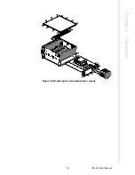
Page 27: ...19 IPC 622 User Manual Chapter 3 Operation Figure 3 8 Replacing the redundant power supply...
Page 28: ...IPC 622 User Manual 20...
Page 36: ...IPC 622 User Manual 28 Table 4 22 PWR1 Pin 1 V12 Pin 4 GND Pin 2 GND Pin 5 V5...
Page 37: ...Appendix A A Exploded Diagram...
Page 39: ...Appendix B B Backplane Options...
Page 41: ...33 IPC 622 User Manual Appendix B Backplane Options...

