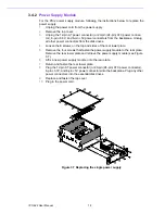
7
IPC-622 User Manual
Chapter 2
S
ystem
Setup
2.2
Backplane Installation
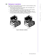
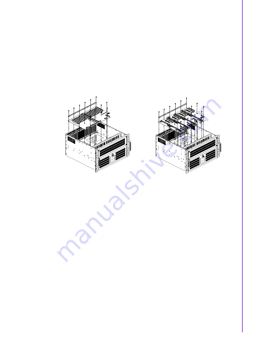
The IPC-622 supports backplanes with up to 20 slots. To install a backplane, please
refer to Figure 2.2 and proceed as follows:
1.
Attach the EMI spring shielding to the backplane. Place the backplane in the
correct location and fasten to the chassis.
2.
For the PICMG1.0 backplane, connect the orange-white wire from connector
HCN1 on the backplane to connector ATXF1 on the CPU card.
3.
Connect the 12-pin AT power connector (to PICMG1.0 backplane), 20-pin (or
24-pin) ATX power connector (to PICMG1.3 backplane), 6-pin +3.3 V, and 6-pin
+5 V power connector from the power supply to the backplane.
Figure 2.2 Backplane installation
PICMG 1.0
PICMG 1.3
Summary of Contents for IPC-622 Series
Page 1: ...User Manual IPC 622 Series 6U Multi Segment Rackmount Industrial Computer Chassis...
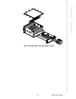
Page 27: ...19 IPC 622 User Manual Chapter 3 Operation Figure 3 8 Replacing the redundant power supply...
Page 28: ...IPC 622 User Manual 20...
Page 36: ...IPC 622 User Manual 28 Table 4 22 PWR1 Pin 1 V12 Pin 4 GND Pin 2 GND Pin 5 V5...
Page 37: ...Appendix A A Exploded Diagram...
Page 39: ...Appendix B B Backplane Options...
Page 41: ...33 IPC 622 User Manual Appendix B Backplane Options...

