GESTEK
Lab
Report No.: 0609083 Rev. 1
N0 3, Pau-Tou-Tsuo Valley, Chia-Pau Tsuen, Lin Kou Hsiang, Taipei County, Taiwan, R.O.C. Tel:886-2-2603-5321 Fax:886-2-2603-5325
Accredited Lab. Of BSMI, NEMKO, NVLAP
Page 12 of 59
Listed Lab. of AUSTEL, Commerce, FCC, VCCI
NVLAP Lab Code:200085-0
4.4 CONDUCTED EMISSION LIMITS
Maximum RF Line Voltage dB(uV)
Frequency
Class A
Class B
MHz QUASI-PEAK
AVERAGE
QUASI-PEAK
AVERAGE
0.15 to 0.50
79
66
66 to 56
56 to 46
0.50 to 5.0
73
60
56
46
5.0 to 30
73
60
60
50
Remarks: In the Above Table, the tighter limit applies at the band edges.
4.5 EUT CONFIGURATION ON MEASUREMENT
4.5.1 FOR POWER LINE
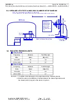
The equipments, which are listed at 4.1, are installed on Conducted Emission Test to meet the
Commission requirement and operating in a manner which tends to maximize its emission
characteristics in a normal application.
The device under test, installed in a representative system as described in section 4.3, was
placed on a non-conductive table whose total height equaled 80 cm. The EUT was powered
through one L.I.S.N. whose the signal output was terminated to the receiver. The other
peripherals were powered from another L.I.S.N. whose the signal output was terminated by 50
Ohms terminator.
4.6 CONDUCTED EMISSION DATA
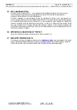
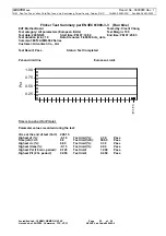
The measurement range of conducted emission, which is from
0.15 MHz to 30 MHz
,
was
investigated. The initial step in collecting conducted data is a spectrum analyzer peak scan of the
measurement range for all the test modes. Then the worst modes were reported the following data
pages.
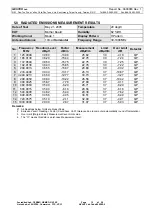
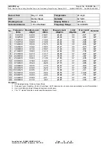
The final measurement equal to Receiver reading plus a Correction factor when AMN insertion
loss bigger than 0.5dB, the receiver added the correction factor to the reading level automatically.
4.7 OPERATING CONDITIONS OF THE EUT
The exercise program used during conducted emission measurement was designed to exercise
the EUT in a manner similar to a typical use. The exercise sequence is listed as below:
1. Setup the EUT and simulators as shown on 4.3
2. Turn on the power of all equipments.
3. Boot the P.C. from Hard Disk and setup the video to windows XP, active all devices.
4. Adjust to appropriate video resolution.
5. Connect the Far End Network Server and run test program “test.bat “.
6. The EUT exchange the information with the GesTek server via HUB.
7. Active other internal devices such as network function.
8. Run “Dell test” and “ H.D.D. R/ W “ test program under windows XP.
9. P.C. sent “H” pattern to monitor, make the “H” pattern full in the screen.
10. P.C. sent “H” pattern to parallel and serial port.
11. Repeat above steps.


